
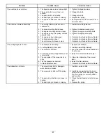


4.
Open the throttle to
FAST
.
Note:
Make sure that the wheel remains
stopped or slightly creeps in reverse; adjust if
necessary.
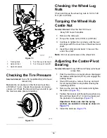
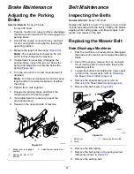
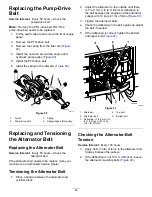
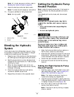
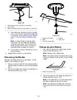
g001070
Figure 99
1.
Tracking knob
4.
Turn this way to track right
2.
Hydraulic tank
5.
Turn this way to track left
3.
Hydraulic pumps
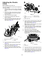
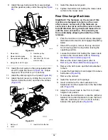
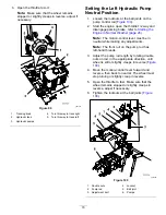
Setting the Left Hydraulic Pump
Neutral Position
1.
Loosen the locknuts at the ball joints on the
pump control rod (
2.
Start the engine, open the throttle 1/2 way and
disengage parking brake; refer to
Engine in Normal Weather (page 26)
.
Note:
The motion-control lever must be in
neutral while making any adjustments.
Note:
The front nut on the pump rod has
left-hand threads.
3.
Adjust the pump rod length by rotating double
nuts on rod, in the appropriate direction, until
wheel is still or slightly creeps in reverse (
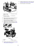
4.
Move the motion-control lever forward and
reverse, then back to neutral. The wheel must
stop turning or slightly creep in reverse.
5.
Open the throttle to fast. Make sure that the
wheel remains stopped or slightly creeps in
reverse, adjust if necessary.
6.
Tighten the locknuts at the ball joints (
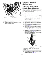
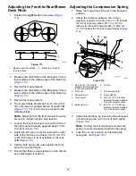
g001066
Figure 100
1.
Double nuts
4.
Locknut
2.
Pump rod
5.
Ball joint
3.
Adjustment bolt
6.
Pumps
70
Summary of Contents for Z Master Professional 7000 Series
Page 2: ......
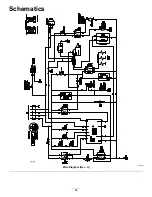
Page 84: ...Schematics g012068 Wire Diagram Rev A 82...
Page 86: ......
Page 177: ...Schaltbilder g012068 Schaltbild Rev A 91...
Page 270: ...Sch mas g012068 Sch ma de c blage Rev A 92...
Page 271: ...Remarques...
Page 272: ...Remarques...
Page 274: ......
Page 362: ...Schema s g012068 Elektrisch schema Rev A 88...
Page 364: ......


