
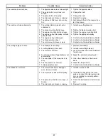
g008932
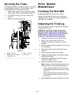
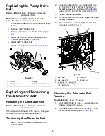
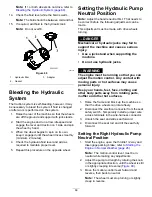
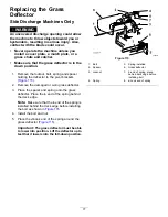
Figure 92
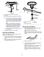
1.
Mounting bolt
2.
Alternator
3.
Increase or decrease the alternator-belt tension.
4.
Tighten the mounting bolts.
5.
Check the deflection of the belt again to ensure
that the tension is correct.
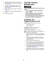
Controls System
Maintenance
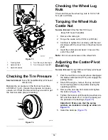
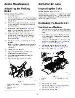
Adjusting the Control
Handle Neutral Position
If the motion-control levers do not align or move easily
into the console notch, adjust the levers. Adjust each
lever, spring, and rod separately.
Note:
The motion-control levers must be installed
correctly.
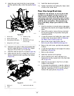
1.
Park the machine on a level surface, disengage
the blade-control switch, and engage the parking
brake.
2.
Shut off the engine, remove the key, and wait
for all moving parts to stop before leaving the
operating position.
3.
Unlatch the seat and tilt the seat forward.
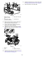
4.
Begin with either the left or right motion-control
lever.
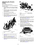
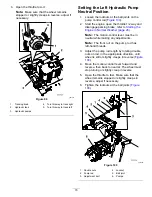
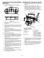
5.
Move the lever to the neutral position but not
locked (
6.
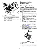
Pull the lever back until the clevis pin (on arm
below pivot shaft) contacts the end of the slot
(just beginning to put pressure on the spring)
as shown in
.
7.
Check where the control lever is relative to the
notch in the console (
Note:
Center the lever so that it pivots outward
to the N
EUTRAL
-
LOCK
position.
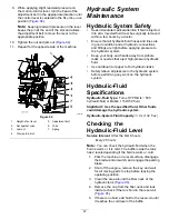
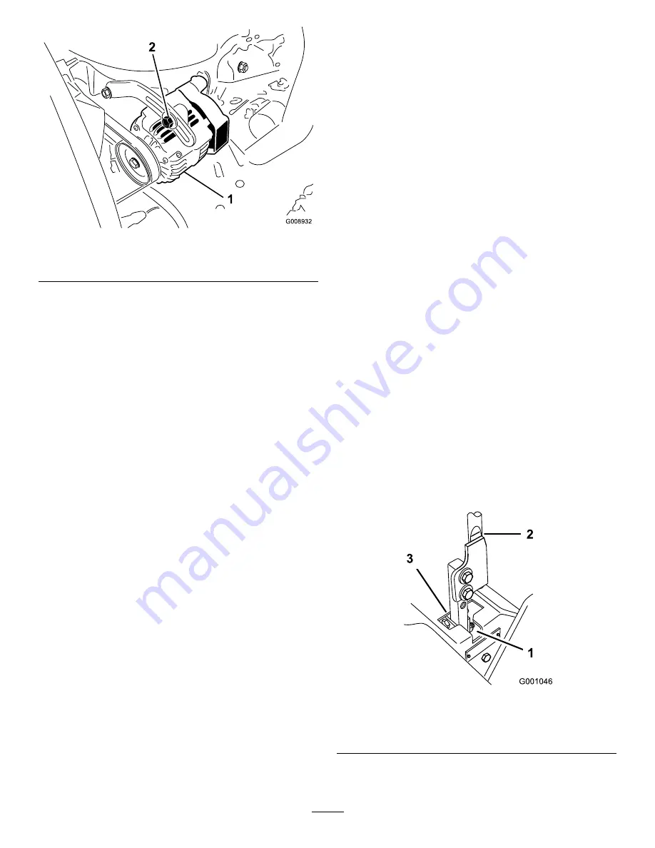
g001046
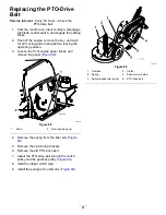
Figure 93
1.
N
EUTRAL
-
LOCK
position
3.
N
EUTRAL
position
2.
Control lever
8.
If adjustment is needed, loosen the nut and jam
nut against the yoke (
66
Summary of Contents for Z Master Professional 7000 Series
Page 2: ......
Page 84: ...Schematics g012068 Wire Diagram Rev A 82...
Page 86: ......
Page 177: ...Schaltbilder g012068 Schaltbild Rev A 91...
Page 270: ...Sch mas g012068 Sch ma de c blage Rev A 92...
Page 271: ...Remarques...
Page 272: ...Remarques...
Page 274: ......
Page 362: ...Schema s g012068 Elektrisch schema Rev A 88...
Page 364: ......


