


Adjusting the Electric
Clutch
Service Interval:
Every 500 hours
The clutch is adjustable to ensure proper engagement
and proper braking.
1.
Park the machine on a level surface, disengage
the blade-control switch, and engage the parking
brake.
2.
Shut off the engine, remove the key, and wait
for all moving parts to stop before leaving the
operating position.
3.
Unlatch the seat and tip it forward.
4.
Loosen the front engine panel knobs and
remove the panel.
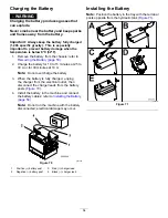
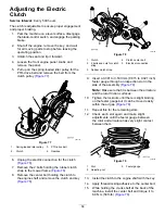
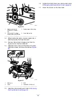
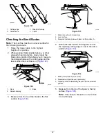
5.
Pull up on the spring-loaded idler pulley for the
PTO-drive belt and remove the belt from the
clutch pulley (
g007167
Figure 77
1.
Spring-loaded idler pulley
3.
PTO-drive belt
2.
Clutch
4.
Gearbox
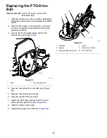
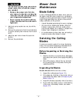
6.
Unplug the electric connection for the clutch
(
).
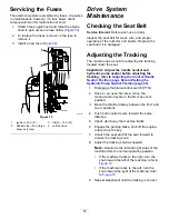
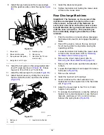
7.
Remove the 2 bolts holding the rubber clutch
strap to the mower frame (
).
8.
Remove the center bolt holding the clutch to
the engine shaft and remove the clutch and key
(
).
g007166
Figure 78
1.
Clutch
4.
Clutch center bolt
2.
2 bolts and nuts for clutch
strap
5.
Electrical connection
3.
Rubber clutch strap
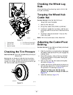
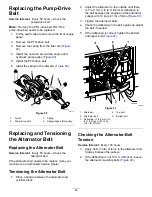
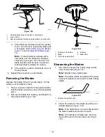
9.
Insert a 0.381 to 0.533 mm (0.015 to 0.021 inch)
feeler gauge through an inspection slot in the
side of the assembly (
).
Note:
Make sure that it is between the armature
and the rotor friction surfaces.
10.
Tighten the locknuts until there is slight binding
on the feeler gauge but it can be moved easily
within the air gap (
).
11.
Repeat this for the remaining slots.
12.
Check each slot again and make slight
adjustments until the feeler gauge between
the rotor and armature has very slight contact
between them.
g007168
Figure 79
1.
Slot
3.
Feeler gauge
2.
Adjusting nut
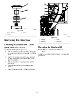
13.
Install the clutch to the engine shaft with the key.
14.
Apply thread-locking adhesive to the center bolt.
15.
While holding the crank shaft at the back of the
machine, install the center bolt and torque it to
68 N∙m (50 ft-lb) (
58
Summary of Contents for Z Master Professional 7000 Series
Page 2: ......
Page 84: ...Schematics g012068 Wire Diagram Rev A 82...
Page 86: ......
Page 177: ...Schaltbilder g012068 Schaltbild Rev A 91...
Page 270: ...Sch mas g012068 Sch ma de c blage Rev A 92...
Page 271: ...Remarques...
Page 272: ...Remarques...
Page 274: ......
Page 362: ...Schema s g012068 Elektrisch schema Rev A 88...
Page 364: ......


