
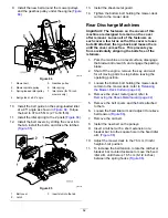
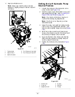
9.
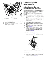
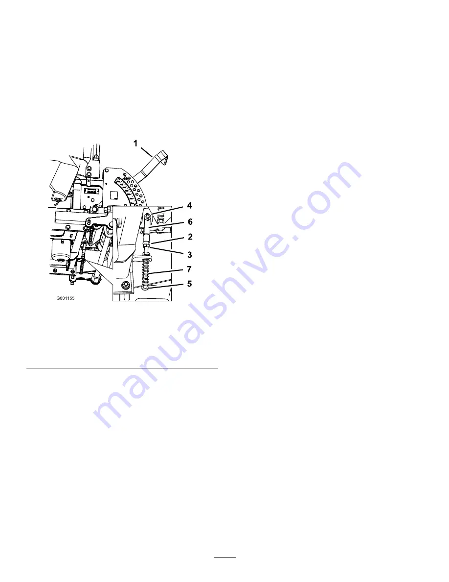
While applying slight rearward pressure on
the motion-control lever, turn the head of the
adjustment bolt in the appropriate direction until
the control lever is centered in the N
EUTRAL
-
LOCK
position (
Note:
Keeping rearward pressure on the lever
keeps the pin at the end of the slot and allows
the adjustment bolt to move the lever to the
appropriate position.
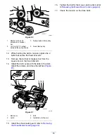
10.
Tighten the nut and jam nut (
11.
Repeat for the opposite side of the machine.
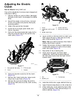
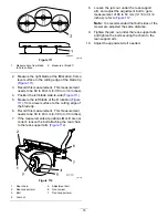
g001155
Figure 94
1.
Height-of-cut lever
5.
Adjustment bolt
2.
Nut against yoke
6.
Yoke
3.
Jam nut
7.
Spring
4.
Clevis pin in slot
Hydraulic System
Maintenance
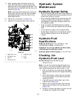
Hydraulic System Safety
•
Seek immediate medical attention if fluid is injected
into skin. Injected fluid must be surgically removed
within a few hours by a doctor.
•
Ensure that all hydraulic-fluid hoses and lines are
in good condition and all hydraulic connections
and fittings are tight before applying pressure to
the hydraulic system.
•
Keep your body and hands away from pinhole
leaks or nozzles that eject high-pressure hydraulic
fluid.
•
Use cardboard or paper to find hydraulic leaks.
•
Safely relieve all pressure in the hydraulic system
before performing any work on the hydraulic
system.
Hydraulic-Fluid
Specifications
Hydraulic-Fluid Type:
Toro
®
HYPR-OIL
™
500
hydraulic fluid or Mobil
®
1 15W-50 fluid
Important:
Use the specified fluid. Other fluids
could damage the hydraulic system.
Hydraulic-System Fluid Capacity:
3.9 L (132 fl oz)
Checking the
Hydraulic-Fluid Level
Service Interval:
After the first 8 hours
Every 25 hours
Note:
You can check the hydraulic fluid when the
fluid is warm or it is cold. The baffle inside the tank
has 2 levels depending if the fluid is warm or cold.
1.
Park the machine on a level surface, disengage
the blade-control switch, and engage the parking
brake.
2.
Shut off the engine, remove the key, and wait
for all moving parts to stop before leaving the
operating position.
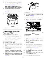
3.
Clean the area around the filler neck of the
hydraulic tank (
4.
Remove the cap from the filler neck and look
inside to check if there is fluid in the reservoir
(
).
5.
If there is no fluid, add fluid to the reservoir until
it reaches the cold level of the baffle.
67
Summary of Contents for Z Master Professional 7000 Series
Page 2: ......
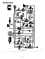
Page 84: ...Schematics g012068 Wire Diagram Rev A 82...
Page 86: ......
Page 177: ...Schaltbilder g012068 Schaltbild Rev A 91...
Page 270: ...Sch mas g012068 Sch ma de c blage Rev A 92...
Page 271: ...Remarques...
Page 272: ...Remarques...
Page 274: ......
Page 362: ...Schema s g012068 Elektrisch schema Rev A 88...
Page 364: ......


