background image

cleaners will remove the ink lines so test your
cleaner before you spray it on your model. You can
remove mistakes with alcohol.You’ll need to touch up
some of the lines from time to time because they
fade with lots of handling and fuel spillage.

APPLY THE  DECALS

The decal sheet provides the detailing and difficult items
shown on the box photo for you to trim your model.

1. Study your documentation package and the

photos on the box to decide where to place 
the decals.

2. Clean your airplane very thoroughly before

applying decals.

3. Cut out the decals and carefully apply them to

your model. You can float the decals into position by
first applying soapy water (just a teaspoon of dish
detergent to a quart of water) to the model’s surface.
Squeegee out the water and soap with a piece of soft
balsa or a credit card wrapped with a tissue. Blot the
surface dry and let the decal cure for at least 12
hours before running the engine.

GET YOUR MODEL READY TO FLY

BALANCE YOUR  MODEL

NOTE: This section is VERY important and must
NOT be omitted! A model that is not properly
balanced will be unstable and possibly unflyable.

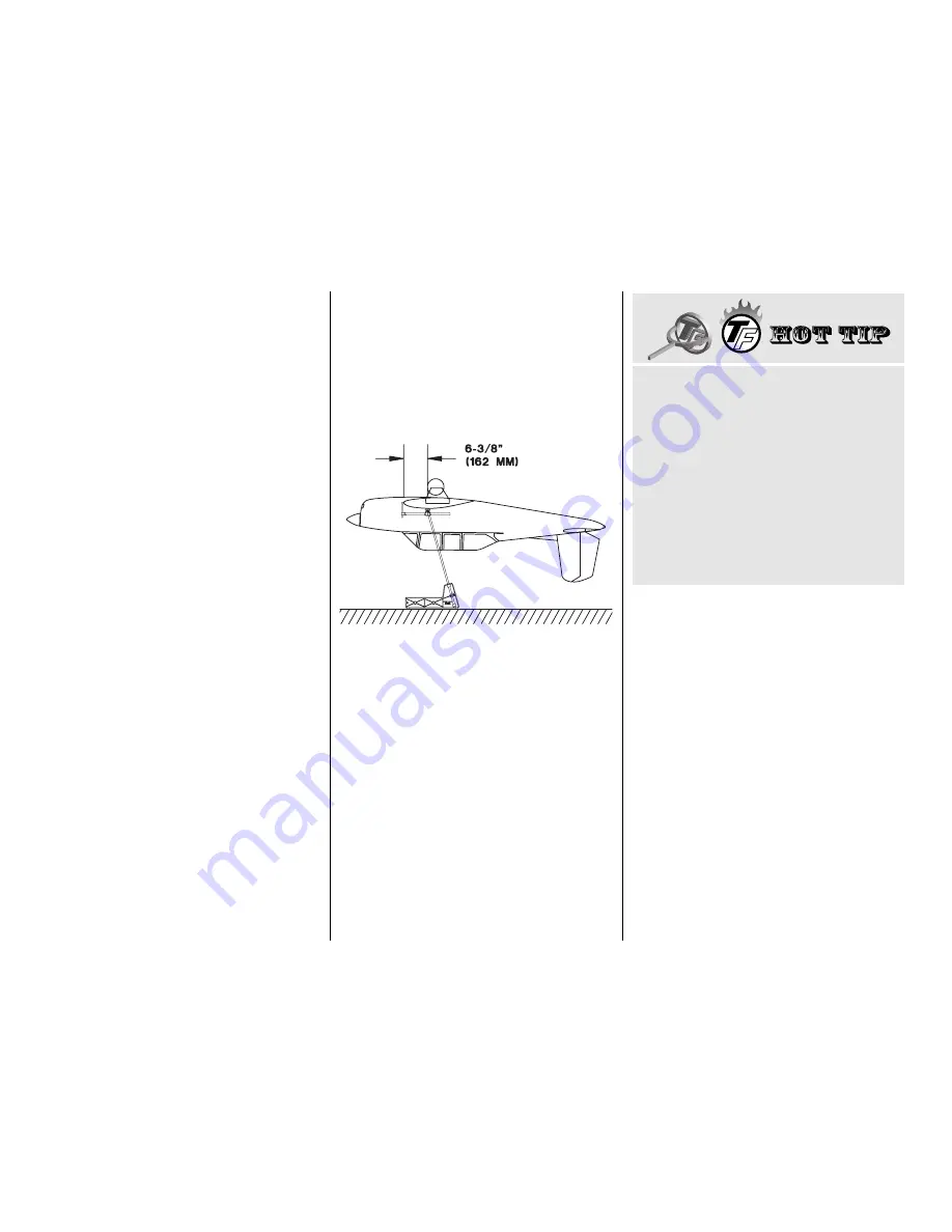
1. See the Hot Tip that follows to accurately mark

the balance point on the top of the wing on both
sides of the fuselage. The balance point is shown on
the plan (CG), and is located 6-3/8” (162 mm) back
from the leading edge at the wing root where it
meets the fuselage side, as shown in the sketch and
on the plan. This is the balance point at which your
model should be balanced for your first flights. Later,
you may experiment by shifting the balance up to
1/2” [12.7mm] forward or 1/4” [6.4mm] back to
change the flying characteristics. If you move the
balance point forward it may improve the
smoothness and tracking, but your T-34B may then
require more speed for takeoff and become more
difficult to slow down for landing. If you move the
balance aft it may make the T-34B more agile with a
lighter feel and allow you to slow the model more for
landing. In any case, please start at the location we
recommend and do not at any time balance your
model outside the recommended range.

2. Temporarily place your receiver and battery

pack inside the fuselage where you plan to mount
them, or lay them on the fuselage over the location
you plan to mount them. This is so you can change
the mounting location of the battery pack or receiver
to change the C.G. without adding any additional
nose or tail weight. Otherwise, all other components
should be in the model and it should be in a ready-
to-fly condition with the fuel tank 

empty

. If you have

installed retractable landing gear, the nose gear
should be retracted.

3. With the wing attached to the fuselage,  lift the

model, inverted, at the balance point. We use the
Great Planes C.G. Machine™ (shown in the sketch)
for this. If the tail drops, the model is tail heavy and
you must shift your battery pack or other
components forward or add weight to the nose. If the
nose drops, it is nose heavy and you must shift your
battery pack or other components aft or add weight
to the tail. In order to save weight, relocate your
battery pack and/or receiver or other components
before you add additional weight to arrive at the
correct C.G. You may easily install nose weight by

HOW TO MARK THE BALANCE POINT

The balance point is measured from the 

center

leading edge

. Since the center section of the

wing is not visible when the wing is on the fuse,
you need to mark the balance point outward a few
inches so you can see where to lift the wing when
it's bolted to the fuse. To do this, mark the balance
point with a felt-tip pen or tape on 

both ends

of

the center section. Place a straightedge across
the marks. Mark the balance point along the
straightedge further out on the wing. Mount the
wing to the fuselage.

-60-

Summary of Contents for T-34B MENTOR

Page 1: ...led product By the act of using the user assembled product the user accepts all resulting liability If the buyer is not prepared to accept the liability associated with the use of this product the buy...

Page 2: ...the belly pan 55 Build and fit the cowl to the fuselage 55 FINISHING 57 Fuel proofing 57 Cockpit details 58 Scale details 58 Final sanding 58 Cover your model with MonoKote film 58 Painting 59 Join th...

Page 3: ...scale models International Miniature Aircraft Association 205 S Hilldale Road Salina KS 67401 913 832 5569 www fly imaa org imaa sanction html Please inspect all parts carefully before you start to b...

Page 4: ...it well Flaps add nicely to the model s flight characteristics and scale appearance while causing no bad effects Only slight trim correction is needed when they are DECISIONS YOU MUST MAKE ENGINE SELE...

Page 5: ...taken from an actual T 34B Mentor Wing Design The Top Flite T 34B Mentor was designed with an I Beam type of wing spar rather than the more traditional D Tube type construction Actually the design co...

Page 6: ...6 DIE CUT PATTERNS IMPORTANT Do not remove the wing ribs or other wing parts from the die cut sheets until instructed to do so...

Page 7: ...7 DIE CUT PATTERNS...

Page 8: ...6161 J Z Products Z RC 56 canopy glue JOZR5007 Microballoons TOPR1090 Milled Fiberglass GPMR6165 Lightweight Hobby Filler HCAR3401 Auto Body Filler Bondo or similar 3M 75 Spray Adhesive MMMR1900 Denat...

Page 9: ...shown on the bottom view is in reference to the centerline of the fuselage Remember this is the bottom view so right thrust is viewed as an offset to the left from the bottom When you get to each step...

Page 10: ...ame procedure to make the wing skins when you build the wing E Press the joining edges of the sheets down with your fingers so they are flat and even D Use a credit card or a piece of thin plywood to...

Page 11: ...bly Place both assemblies over the plan and add the LE brace See the photo at step 4 4 Use a small square to align the stab TE spar at rib S2S over the plan Pin rib S2S over its location on the plan w...

Page 12: ...and the top of the leading edges stab and elevator spars and the TE brace so they match the contour of the ribs Do not change the shape of the airfoil by sanding too much 16 THIS STEP IS VERY IMPORTAN...

Page 13: ...spar and the elevator LE spar where shown on the plan Glue the die cut 1 8 3 2mm balsa stab gusset to the hinge block and rib S7S as shown on the plan Position the gusset so it is even with the botto...

Page 14: ...en 40 Draw a centerline all the way around a 3 4 19mm shaped balsa stab tip block We HIGHLY recommend that you use the Great Plans Slot Machine for cutting your hinge slots This motorized hinge slotti...

Page 15: ...ill hold the elevator tip while you shape it Note When you shape the left stab tip in addition to the plan use the finished tip on the right stab as a guide to shape the left stab tip This way you can...

Page 16: ...s so the top edge of the LE is even with the top of the ribs The bottom of the LE will extend below the bottom of the ribs but will be sanded flush later 7 Sand the upward facing edges of the leading...

Page 17: ...e LE of the rudder Sand the bottom of the rudder even with rib R1A 23 Glue a die cut 1 8 3 2mm balsa fin trailing edge R9 to the fin TE spar and a die cut 1 8 3 2mm balsa rudder leading edge R9 to the...

Page 18: ...f left wing ribs the same way but use the photo above to make sure you glue the doublers to the correct side of the ribs R4 Remove the shaded area of balsa shown in the previous two photos after the e...

Page 19: ...when it is time to join the wing BUILD THE OUTER WING PANELS For clarity some of the photos show the wing off the building board without the plan but of course you should build your wing over the pla...

Page 20: ...all the ribs with the plan and pin them to your building board In addition to T pins place weights on top of the ribs and the aft spars to insure that all the jig tabs are contacting your building boa...

Page 21: ...ll the jig tabs are contacting your building board when you remove the T pins you may leave the T pins out of the jig tabs In this case the weights that will be used to hold the sheeting to the ribs w...

Page 22: ...10 Clean the glue blobs and wood chips off your workbench so they won t leave dents in your beautiful wing sheeting Turn the wing over and carefully cut the jig tabs off the ribs 11 Reinforce all glue...

Page 23: ...heel If necessary enlarge the clearance holes in the ribs and doublers so the air cylinder and the strut do not interfere with the ribs R10 Cut along the line you started earlier on rib W3 for the whe...

Page 24: ...y fit against the ribs as shown on the plan Bevel the tops of the hinge blocks that fit in the aileron so they match the angle of the ribs Glue the hinge blocks in the wing and aileron 22 Use a bar sa...

Page 25: ...lywood wing bolt plates together to make two 1 4 6 4mm plates 5 Glue the die cut 1 8 3 2mm plywood leading edge doubler W21 to the die cut 1 8 3 2mm plywood center leading edge W21A so the bottoms of...

Page 26: ...skin and one 11 x 9 279 4 x 228 6mm aft top center section wing skin 4 Sand the sheets so they are flat and smooth Trim the forward skin so the aft edge aligns with the center of the top spar and the...

Page 27: ...so you understand the procedure and can gather the items you will need 6 Mix a batch of 45 or 30 minute epoxy Spread a film of epoxy in the outer wing panel everywhere it contacts the dihedral braces...

Page 28: ...bottom wing skins the same way you made the top wing skins on page 18 2 Use a ballpoint pen to mark the top sheeting over ribs W14 W9 and W4 at the leading and trailing edges Check all glue joints an...

Page 29: ...shape the wing tip Inspect your progress frequently Use the plan and the above photo as a reference so you know what the curve of the tip should look like Note When you shape the second wing tip use t...

Page 30: ...the flap horn at the location shown on the plan The hole should be biased toward the top of the wing 6 Place the flap over the plan and mark the location of the die cut 1 16 1 6mm ply flap horn Fit bu...

Page 31: ...ing over each hinge block you marked them before you sheeted the bottom of the wing and drill 3 16 4 8mm holes 1 1 8 28 6mm deep for the Hinge Points Hint Instead of using a drill bit use a piece of 3...

Page 32: ...he left wing panel the same way MOUNTTHE FLAP AND AILERON SERVOS 1 Cut the openings in the bottom of the wing sheeting for the die cut 1 16 1 6mm plywood aileron and flap servo hatch covers if you re...

Page 33: ...o check the dihedral before you permanently glue the wings together clamp the wing together raise the center section off your workbench with balsa sticks of equal size so the wing is not resting on th...

Page 34: ...bottom view of the fuselage 2 Use 30 minute epoxy to glue two die cut 1 8 3 2mm plywood F1B s together and F1T to the front of F1DT there are two F1DT s included in the kit but only one is used Make s...

Page 35: ...can see the splice in the following photo 4 Position but do not glue formers F1 through F11 on the side stringers so the embossed names on the formers face forward Adjust the stringers as needed Are...

Page 36: ...mately 1 2 12 7mm Glue the tube to the formers this tube is visible in the photo at step 5 2 Before they are installed in the fuselage test fit your servos in the aft servo trays to make sure they fit...

Page 37: ...gers Mark the wing saddle and corner stringer on the sheet Trim the sheet about 3 16 4 8mm outside of the lines Note The side sheet will not reach all the way back to the end of the fuselage We will i...

Page 38: ...on the elevator joiner wire and the rudder torque rod 6 Mark the center of the stab 1 1 8 28 6mm from the TE Drill a 1 8 3 2mm hole through the center of the stab at the mark Use the die cut 1 8 3 2m...

Page 39: ...ods into the guide tubes Slide a silicone retainer onto a nylon clevis and thread the clevis onto the wire about 15 full turns Make a second pushrod the same way 12 Cut the rudder pushrod tube on the...

Page 40: ...the epoxy cures confirm alignment once more using the pin and string technique Do not proceed until the epoxy has fully cured MOUNT THE FIN 1 If you have not already done so sand the sheeting on the b...

Page 41: ...ers so they blend together 4 The turtle deck is sheeted with four 1 16 1 6mm balsa sheets one sheet on the bottom of each side of the turtle deck and one sheet on the top of each side of the turtle de...

Page 42: ...center of the top center stringer Trim the aft end of the sheet so it fits the fin and ends at former F10A Glue the sheet in position Make a wedge from a 1 16 1 6mm leftover piece of balsa to fit betw...

Page 43: ...silicone retainer to the elevator control horn and fit the rudder and elevator in place 2 Place a servo arm on your rudder and elevator servos With the servos centered and the rudder and elevators neu...

Page 44: ...elevator joiner wire Fit the tail cone on the aft end of the fuselage and drill two 1 16 holes on each side Remove the tail cone and enlarge the holes in the tail cone only with a 3 32 drill bit Harde...

Page 45: ...k block of wood on the back so the drill does not split the wood when it comes through 7 Press four 8 32 blind nuts into the 7 32 5 6mm holes on the back of the firewall Use an 8 32 x 1 1 2 38 1mm soc...

Page 46: ...the plan Mark the location of the 1 4 6 4mm plywood landing gear rails onto the braces F3 Remove the engine mount from the firewall F4 Cut a bevel on the end of the 1 4 x 9 16 x 9 6 4 x 14 3 x 228 6m...

Page 47: ...o securely hold the set screws That was easy wasn t it Now hook up the throttle It s just as easy Skip to Hook Up The Throttle on page 49 R3 Temporarily place the landing gear rails through the firewa...

Page 48: ...the left side of the servo tray as shown in the photo Note that the servo is offset toward the aft edge of the servo tray the side you cut off R10 If you would like to mount your air control valve in...

Page 49: ...l socket 0 80 threaded ball and 0 80 nut Use a drop of thread lock on the nut Glue the throttle servo tray to the rails Secure the throttle servo to the tray with the hardware that came with the servo...

Page 50: ...ock on one side of the wing with a 7 drill Keep the drill bit perpendicular to the wing bolt plate as you drill so the head of the wing bolt will rest flat 8 Remove the wing and tap threads into the w...

Page 51: ...ue the die cut 1 8 3 2mm plywood formers F1A and F2A in place as shown on the plan F1A is positioned 2 51mm forward of F2 F2A is positioned 3 16 4 7mm forward of F2 5 Glue the die cut 1 8 3 2mm plywoo...

Page 52: ...edges of the vertical slit to fit the slit together At the front of the fuselage slit the sheet vertically at F2 and glue it in place in the same manner You will find this surprisingly easy to do Not...

Page 53: ...kit TOPQ8413 in your T 34B you can skip the next step and follow the instructions supplied with the cockpit kit 2 Fit and glue two die cut 1 8 ply instrument panels in place where shown on the plans...

Page 54: ...ectors and air lines if you are installing retracts The servo extension cords don t have to be connected to the servos and the air lines don t have to be connected to the retracts but they should be i...

Page 55: ...x 35 x 38 1mm wing fairing blocks to match the curvature of the right side of the fuse at the leading edge of the wing Bolt the wing to the fuse Sand the side and rear of the wing fairing block so it...

Page 56: ...t unit 6 Test fit eight 1 2 x 1 2 x 5 8 12 7 x 12 7 x 15 9mm maple cowl mount blocks in the notches in the cowl ring Sand the blocks so they match the shape of the cowl Glue them in place Mark the cen...

Page 57: ...to fill one seam at a time 4 Use an expired credit card or a piece of plastic as a spatula to apply Bondo Bend your spatula to build up a slight mound over the seam 5 Apply only enough Bondo to fill t...

Page 58: ...pon the sheeting for its strength Modelers who do this tend to cut into the sheeting and this will weaken the structure 2 Remove all dust from the structure with a vacuum with a brush attachment compr...

Page 59: ...gap between the elevators and the stab so you do not glue them together 6 Cut a paper towel into 2 50 8mm squares Add six drops of thin CA to the center of the hinges on both the top and bottom Use t...

Page 60: ...takeoff and become more difficult to slow down for landing If you move the balance aft it may make the T 34B more agile with a lighter feel and allow you to slow the model more for landing In any case...

Page 61: ...ther maneuvers INSTALL YOUR RECEIVER BATTERY PACK AND RETRACT COMPONENTS The location of your receiver and battery pack may be determined by the C G On our prototypes we mounted the battery pack and r...

Page 62: ...portant for the flaps Center the trims and put the servo arms back on your servos and secure them with the screw 10 While you re at it double check all the servos and make sure the servo arms are secu...

Page 63: ...ctly do not fly Find and correct the problem first Look for loose servo connections or broken wires corroded wires on old servo connectors poor solder joints in your battery pack or a defective cell i...

Page 64: ...recommend using the low rate settings as listed on page 62 High rate elevator may be required for crisp snap rolls and spins With a 1 20 engine the T 34B really scoots along so you should manage the...

Page 65: ...This model belongs to Name Address City State Zip Phone number AMA number C B Cut this placard out fill it in and place it inside your model...

Page 66: ...4 4 1 0 0 F U E L U S E 1 0 0 1 3 0 G R A D E F U E L O R H I G H E R O N L Y C A P A C I T Y 2 5 U S G A L L O N S C A U T I O N D O N O T I N S E R T F U E L N O Z Z L E M O R E T H A N 3 I N T O T...

Reviews: