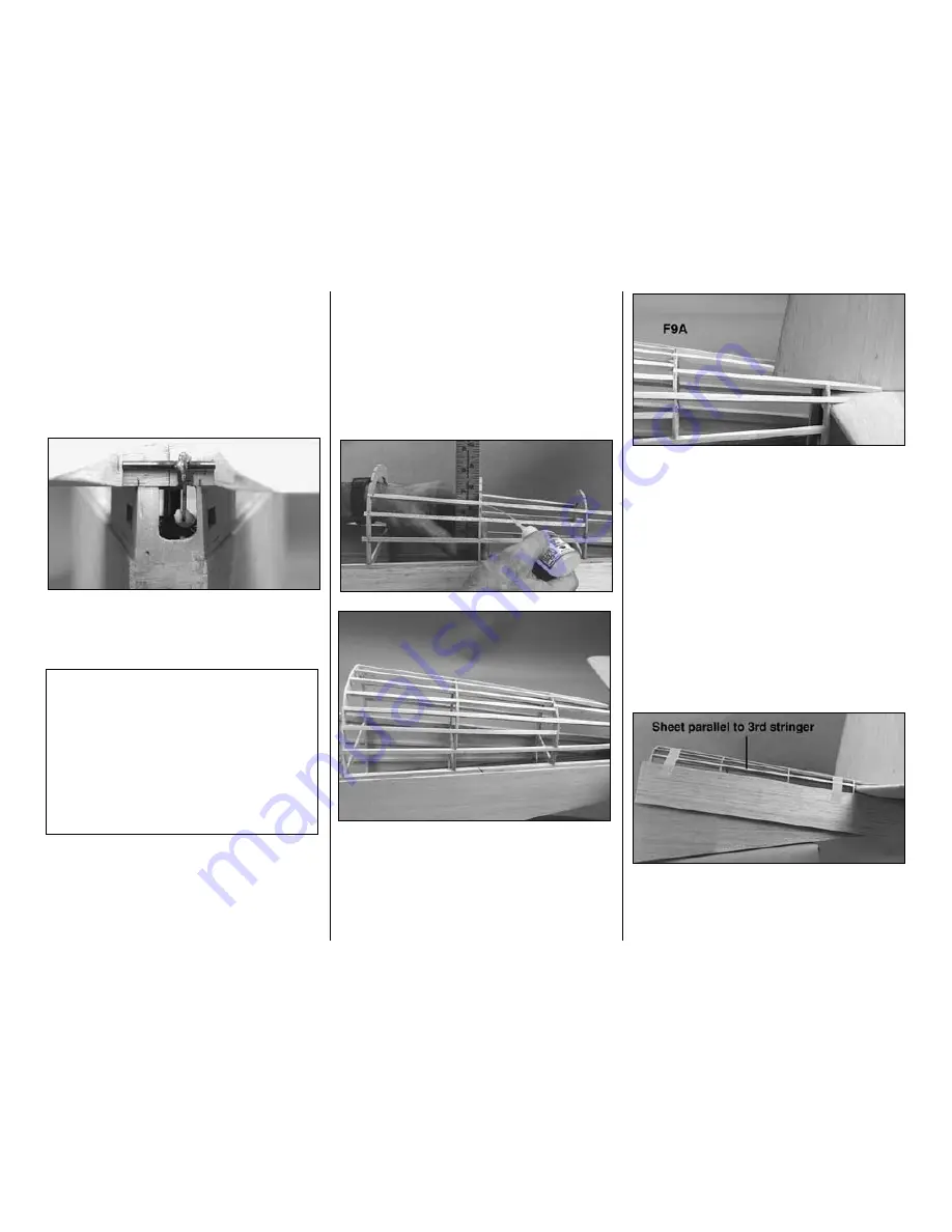
Recheck that the fin is
vertical
in relation to the stab
and that the TE of the fin is
perpendicular
to the
main fuselage stringer. Also check that the TE of the
fin is against the rudder torque rod and that the rod
is in the
center
of the fin TE. Use masking tape to
hold the fin in position until the epoxy is fully cured.
Note:
Be very careful not to get any epoxy on the rudder
torque rod or in the torque rod hole in the stab.
❏
5. Test fit the rudder and elevator and temporarily
hook up the pushrods. Make sure you can move the
controls without any interference or binding. Make
adjustments if necessary.
BUILD THE TURTLE DECK
❏
1. Glue the die-cut 1/8” [3.2mm] ply formers
F7A,
F8A
and
F9A
to the tops of their respective formers.
❏
2. Cut the
turtle deck stringers
from seven 3/16”
x 3/16” x 30” [4.8 x 4.8 x 762mm] balsa sticks. Glue
the stringers into the notches of the formers as
shown on the fuselage plan and in the photo. Note
the arrangement of the stringers at F9A.
Important:
Align the formers with a straightedge as
you glue the stringers to them.
❏
3. Sand the stringers and formers so they
blend together.
❏
4. The turtle deck is sheeted with four 1/16”
[1.6mm] balsa sheets–one sheet on the bottom of
each side of the turtle deck and one sheet on the top
of each side of the turtle deck. Examine the four
1/16” x 3” x 24” [1.6 x 76.2 x 610mm] balsa sheets
and set the two softest sheets aside to be used for
the top.
Caution:
To save weight in the aft end of the model,
the turtle deck is sheeted with 1/16” [1.6mm] balsa.
Be careful installing the sheeting so that it will not
require an excessive amount of sanding.
❏ ❏
5. Cut one of the bottom turtle deck sheets to a
length of 21-1/2” [546mm]. Position the sheet on the
left side of the turtle deck so the top edge contacts
the bottom of the stab and is parallel to the third
stringer from the bottom as shown in the photo.
T-34B Fact:
When the Navy evaluated the T-34,
they selected it as the best trainer available. They
could not just adopt the Air Force version,
however, as this would require them to share the
R&D costs. They made enough changes to the
aircraft that it could be classified as a “new”
model, the T-34B. While the changes were minor,
they did have an affect on the way the aircraft
handled. The dihedral of the wing was increased
by one degree and a spring system was added to
increase elevator stick forces.
-41-
Summary of Contents for T-34B MENTOR
Page 7: ...7 DIE CUT PATTERNS...


