❏
8. Return to step 1 and glue another side sheet to
the left fuse side the same way.
❏
9. Add pieces of leftover 3/32” [2.4mm] balsa to
extend the side sheets to the end of the fuselage.
See the photo at step 11.
❏
10. Remove the T-pins and lift the fuselage from
your building board. Reinforce glue joints you
couldn’t reach earlier or those that don’t look strong.
❏
11. Trim, then sand the fuselage side sheeting and
stringers that extend aft of former F11 so they are flush.
MOUNT THE STAB AND FIN
Note:
Build accurately during the next few steps. The
stab saddle and the aft formers align the stab and
set the incidence, which will greatly affect the way
your model flies.
Use this photo for the next three steps.
❏
1. Glue the die-cut 1/8” [3.2mm] balsa
aft upper
former F11A
to former F11.
❏
2. Securely glue the die-cut 1/8” [3.2mm] plywood
stab saddles
to the top of the main fuse side
stringer and F11A.
❏
3. Glue the die-cut 1/8” [3.2mm] plywood
upper
former F10A
to the top of former F10. Glue the front
of the stab saddles to F10A.
❏
4. Use a bar sander with 80-grit sandpaper to sand
the
front
of the stab so the
TE will align with F11A when
it is placed on the stab saddle.
❏
5. Use a hobby knife or a Multi-Pro
™
with a
sanding drum to cut F11A to clear the horn on the
elevator joiner wire and the rudder torque rod.
❏
6. Mark the
center
of the stab 1-1/8” [28.6mm]
from the TE. Drill a 1/8” [3.2mm] hole through the
center of the stab at the mark. Use the die-cut 1/8”
[3.2mm] ply
90 degree gauge
as a guide to keep the
drill straight.
Hint:
A 6” [152mm] piece of 1/8”
[3.2mm] brass tube sharpened at one end cuts a
clean hole.
Note
: You must make sure you are drilling
in the center of the stab as you are drilling into the two
center 3/32” [2.4mm] ribs. Clean away any glue in the
joint so that the drill will get a clean start into the hole.
❏
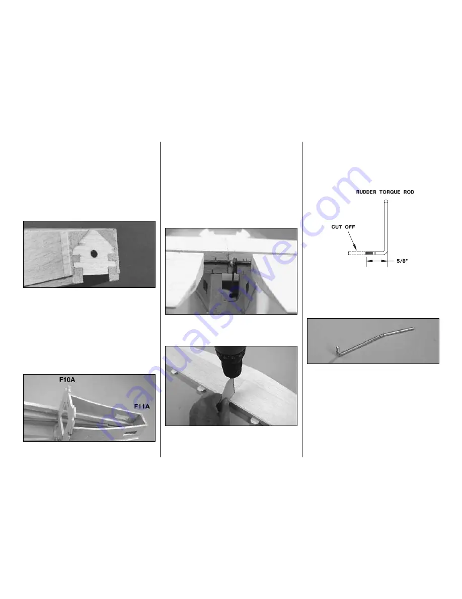
7. Cut the threaded end of the
rudder torque rod
so the threads extend 5/8” [15.9mm] as in the sketch.
Tap threads in the nylon
swivel horn
with a 6-32 tap.
Thread it onto the rudder torque rod until it is even
with the end.
❏
8. The rudder torque rod must be bent 90 degrees
after
it is inserted through the stab. Make a mark on
the torque rod 2-1/2” [63.5mm] from the threaded
end of the rod. Place the torque rod on the side view
of the fuselage plan to confirm the mark is in the
correct place. Notice in the above photo that we have
made a
slight bend in the torque rod. This will help
insure that the 90 degree bend is made in the proper
direction in the next step. Also, notice the orientation
of the threaded end of the torque rod.
Caution:
Once
installed in the stab, the threaded end of the rod
must point to the left side and the 90 degree bend
must face aft into the rudder.
-38-
Summary of Contents for T-34B MENTOR
Page 7: ...7 DIE CUT PATTERNS...


