58
Kalypso Reference Manual
Section 1 — System Overview
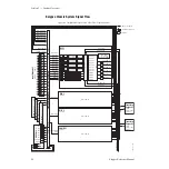
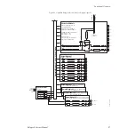
Kalypso HD System Signal Flow
Figure 46. Simplified Kalypso HD Video Flow Diagram
8210_00_01_r1
Key 1 Keyer/
Chromakeyer
Borderline
Borderline
Borderline
Borderline
Key 2 Keyer/
Chromakeyer
Key 3 Keyer/
Chromakeyer
Key 4 Keyer/
Chromakeyer
Video Processor
Video Processor
Video Processor
Video Processor
Effects Send Switch
Key 1 Fill
Key 1 Cut
Key 2 Fill
Key 2 Cut
Key 3 Fill
Key 3 Cut
Key 4 Fill
Key 4 Cut
Bkgnd A
Bkgnd B
Utility 1
Utility 2
Program D
Preview A
Preview 2
Program A
Program B
Program C
Wipe Pattern
Generators
2 Complex, 4 Simple
Input Crosspoint
1
2
3
4
5
6
7
8
9
10
85
86
87
88
89
90
80
81
82
83
84
Mixer
PGM/PST Program A
PGM/PST Program B
PGM/PST Program C
PGM/PST Program D
PGM/PST Preview A
PGM/PST Preview 2
Ch 1
Ch 2
Ch 3
Ch 4
Ch 5
Ch 6
Pvw Video
Pvw Key
In 1
In 2
Still Store
Option
Eff. Return
Eff. Send
M/E 1 Outputs
M/E 2 Outputs
M/E 3 Outputs
M/E 1
Inputs
Transform
Engine #1
Option
3 Video + 3 Key
Channels
Transform
Engine #2
Option
3 Video + 3 Key
Channels
M/E 1
Inputs
Key 1 Fill
Key 1 Cut
Key 2 Fill
Key 2 Cut
Key 3 Fill
Key 3 Cut
Key 4 Fill
Key 4 Cut
A Video
B Video
Utility 1
Utility 2
Deserializer
and Reclock
Video or
Key Signals
Serializer
90
External
Inputs
12 Dual
Outputs Per
M/E Module
Bkg 1
Bkg 2
Test
Black
Checksum & Timing
Diagnostic Data to
Control Processor
Serial Reference to Sync Generator
Dual Outputs
13 - 24
Dual Outputs
25 - 36
Dual Outputs
37 - 48
134 x 100 Crosspoint Matrix
Variable Delay
1
Variable Delay
2
Variable Delay
3
Variable Delay
4
Variable Delay
5
Variable Delay
6
Variable Delay
7
Variable Delay
8
Variable Delay
9
Variable Delay
10
Variable Delay
11
Variable Delay
12
M/E 2 - Output
(Same as PGM/PST)
M/E 3
Inputs
PGM/PST - Output
(Same as PGM/PST)
M/E 2
Inputs
M/E 3 - Output
(Same as PGM/PST)
M/E 1 - Output


