Operating Instructions
34
Microprocessor On/Off Switch:
This switch supplies or
removes electrical power to the microprocessor. The
Microprocessor Power Switch is located above HMI Control
Panel. It is hidden when the lower roadside body panel
surrounding the Control Box is closed. If the unit is not going
to be used for an extended period of time, turn the
Microprocessor On/Off Power Switch to the OFF position to
maximize battery life.
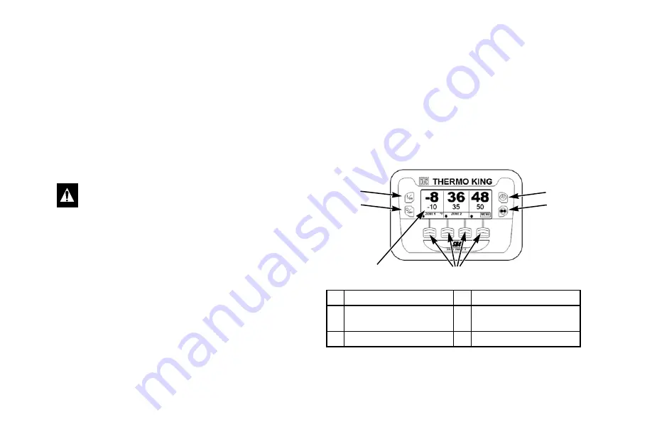
Control Panel
The control panel has a display and eight touch sensitive keys.
The display is capable of showing both text and graphics. The
four keys on the left and right sides of the display are “hard”
(dedicated) keys. The four keys under the display are “soft”
keys. The function of “soft” keys change depending on the
operation being performed. If a soft key is active, its function
will be shown in the display directly above the key.
Control Panel Display
The display presents information to the operator. This
information can include setpoint and temperature for each
zone, unit or zone operating information, gauge readings,
temperatures and other information as selected by the operator.
The default display is called the Standard Display. It is shown
in Figure 2 and will be described in detail later in this chapter.
WARNING: The unit can start at any time without
warning. Press the
O
FF
key on the control panel and
place the microprocessor On/Off switch in the Off
position before inspecting or servicing any part of the
unit.
1. On Key (Hard Key)
4. Defrost Key (Hard Key)
2. Off Key (Hard Key)
5. Cycle-Sentry/Continuous
Mode Key (Hard Key)
3. Display
6. Soft Keys
Figure 2: Control Panel Display and Keys
1
2
3
4
5
6
Summary of Contents for Precedent C-600M
Page 2: ......
Page 58: ...Operating Instructions 56 Figure 44 Initiating a Manual Defrost Cycle Defrost Key...
Page 71: ...Operating Instructions 69 Figure 61 Performing a Pretrip Test 2 From Figure 60...
Page 85: ...Operating Instructions 83 Figure 83 Displaying and Clearing Alarm Codes 1 See Figure 84...
Page 86: ...Operating Instructions 84 Figure 84 Displaying and Clearing Alarm Codes 2 From Figure 83...
Page 165: ......


