background image

Instruction manual for MH & MH+M 


23


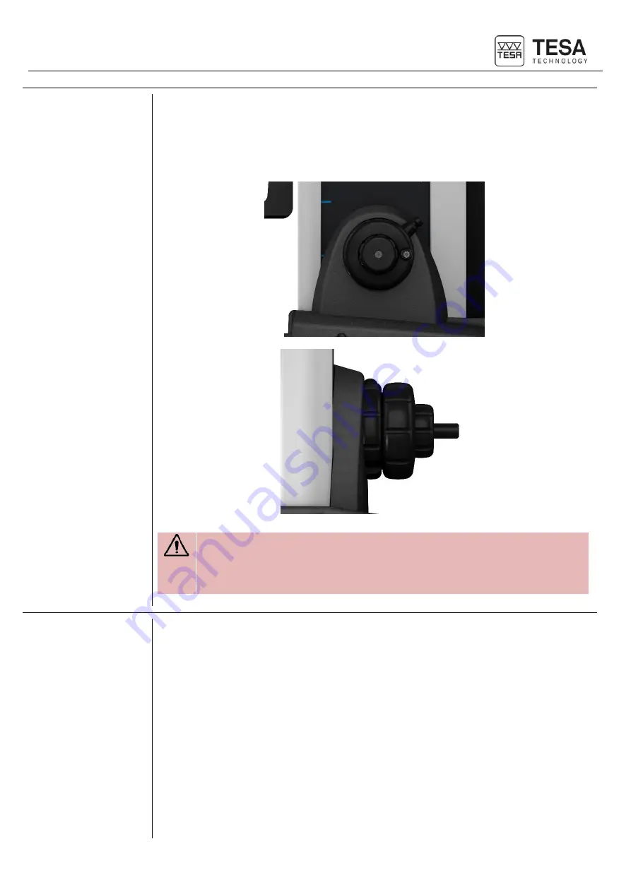
4.3  Fine adjustment 

system


Certain height gauge models also include a fine adjustment system for precise and sensitive 
displacement of the probe: 


00730076 MICRO-HITE 350F 


00730077 MICRO-HITE 600F 


00730078 MICRO-HITE 900F 


A manual MICRO-HITE that does not include this system can be upgraded at 
any time. 
 
For further information, please contact your local reseller. 


4.4  Calibration 

certificate


Each MICRO-HITE and MICRO-HITE+M is provided with an individual calibration certificate. 
The  number  of  the  certificate  is  the  same  as  the  serial  number  of  the  instrument,  as  it  is 
indicated on its label. If the two numbers are not the same, please contact your local reseller. 
 
The documented measuring results of the calibration certificate refer to the condition of the 
instrument  during  its  final  inspection  in  the  factory  of  TESA.  The  results  obtained  and  the 
technical specifications indicated depend on the environmental factors. If the instrument is not 
used in ideal conditions, it is very likely that its performances will be downgraded. 


Summary of Contents for MICRO-HITE

Page 1: ...This document is confidential and only to be used internally by the company that has purchased one of the height gauges mentioned above Before duplicating or transmitting it to third parties without any connection to the use of these instruments an official request has to be sent to TESA SA ...

Page 2: ...wer supply 16 2 9 Measuring system 16 2 10 Control panel 18 2 11 Fixing arm 18 2 12 Information LED 19 2 13 Interface displayed values 19 2 14 Printer 19 2 15 Connectors 20 3 TECHNICAL SPECIFICATIONS 21 4 DELIVERY CONTENTS 22 4 1 System components 22 4 2 Packaging 22 4 3 Fine adjustment system 23 4 4 Calibration certificate 23 5 INSTALLATION SECURITY MAINTENANCE 27 5 1 Location 27 5 2 Place of use...

Page 3: ...mised language 55 10 INITIALISATION 56 10 1 Concept 56 10 2 Automatic process MH M 56 10 3 Manual process MH 56 11 DETERMINATION OF THE PROBE CONSTANT 58 11 1 Masterpiece 58 11 2 Concept 58 11 3 Procedure 60 11 4 Steps 60 12 PRINCIPLES OF MEASUREMENT 63 12 1 Generality 63 12 2 Probe support 63 12 3 Measurement modes 63 12 4 ST1 ST2 philosophy 64 12 5 Measurement functions 65 12 6 Manual single pro...

Page 4: ... MODE 95 15 1 Introduction 95 15 2 Fine adjustment 95 15 3 Measurement principle MH M 95 15 4 Measurement principle MH 97 15 5 Graph 98 16 ANGLE MEASUREMENT 100 16 1 Introduction 100 16 2 Measurement principle MH M 100 16 3 Measurement principle MH 102 16 4 Cone angle measurement principle 103 17 CALCULATOR 104 17 1 Generality 104 17 2 Concept 104 17 3 Use of the measurement blocks 105 17 4 Changi...

Page 5: ...25 Origin translation 130 19 26 Datum rotation 131 19 27 How to integrate a result from the 2D mode into a measurement program 132 20 ZZ MODE 134 20 1 Generality 134 20 2 Operating principle 134 21 DATA MANAGEMENT 136 21 1 Generality 136 21 2 Automatic or manual transmission 136 21 3 Transmission format 137 21 4 Transmission via TLC cable 138 21 5 Transmission via TLC wireless 139 21 6 Use of the ...

Page 6: ...trol 154 23 6 Software update 154 24 CONTEXT BASED ACTIONS 157 24 1 General actions 157 24 2 Actions regarding ST1 ST2 modes 158 24 3 Actions regarding Perpendicularity mode 158 24 4 Actions regarding Angle mode 158 24 5 Actions regarding Min max Δ mode 159 24 6 Actions regarding 2D mode 159 24 7 Actions regarding Calculator mode 159 OPTIONAL ACCESSORIES 160 EXAMPLE TESA WORKPIECE 163 ...

Page 7: ...e content of this document has been created subject to subsequent modifications without prior notice All modification rights are reserved The French version is the reference language All other language versions are only translations 1 4 Copyright software The software delivered with MICRO HITE or MICRO HITE M contains copyright protected software that is licensed under the following open source li...

Page 8: ... of manual height gauges to easily use an automatic height gauge and vice versa 1 6 Symbols Several different types of symbols are used in this manual They give important information that has to be taken into account in order to correctly use the measuring instrument Position Description Not adhering to these instructions can lead to incorrect measurement results Corresponds to an assistance for b...

Page 9: ...des on the guiding element while the optoelectronic measuring system patented by TESA measures any head displacement Each height gauge is used with a control panel No 14 with numerous calculation possibilities offering a measuring solution adjusted to each application Therefore each instrument features several patented technologies which makes it a reliable and unique tool that can be used by any ...

Page 10: ...Instruction manual for MH MH M 10 Fig Description of the constitutive elements of the TESA MICRO HITE M ...

Page 11: ...s form a large surface so that any grooves or other similar irregularities on the granite table can be easily cleared The faces 9 defined by the red zones in the schema below are specially designed to support the instrument against a parallel gauge block or for guiding it along such a block 2 3 Air cushion The air cushion which is generated by an integrated electric pump allows the height gauge to...

Page 12: ...t the height gauge can be moved by using the air cushion Experience has shown that the air cushion should not be thicker than necessary When it is activated it has to support the weight of the instrument while still being slightly in contact with the granite table 2 4 Vertical column The rigid vertical column of the instrument is perpendicular to the cast iron base to which it is permanently fixed...

Page 13: ...t when it is moved on the air cushion and for starting the fast displacement of the probe as well as for triggering all main measuring functions up or down probing bore or shaft measurement The height gauge is very user friendly with easy and precise handling Any fast displacement slow approach to the point to be measured probing up and down or bore measurement can be carried out using this rotary...

Page 14: ...o the rotation angle It will decelerate and then stop when approaching the zero point or when releasing the rotary control handle The rotation window between and is considered as the speed window that corresponds to the position of the probe Fast displacement In case of a large distance between two points to be measured you can move the probe in such way that the displacement time between two meas...

Page 15: ...the one of the movement or by pressing one of the keys of the control panel keyboard 2 6 Handwheel On manual models the main handwheel located above the base is the element that allows you to move the probe during a measurement The handwheel can include a fine adjustment system which allows to adjust the displacement to the measurement of small elements A manual MICRO HITE that does not include th...

Page 16: ...ring system digitally capturing the measured length which is also called measurand TESA patent The glass scale with both incremental graduations and a reference mark serve as material measure According to a principle of reflection the scale is scanned by a sensor with no mechanical contact The measuring signal is then transmitted to the control panel From the neutral position A the system for dete...

Page 17: ...ark corresponds to the minimum required pressure in order to have a single probing be taken If the pressure is not high enough the bar colour is orange When the mark has been passed by the displayed force the colour becomes green or even red if the pressure is too high Two horizontal lines are also displayed in the middle of the bar They represent the ends of the measurement zone defined by letter...

Page 18: ...using on particular actions For further details see this chapter 2 11 Fixing arm As all environments the instrument is used in are different your system includes a flexible control panel support which offers you two degrees of freedom through adjustable screws Then it is possible to adapt the angle of the screen for easier reading position the control panel for an ideal ergonomic use ...

Page 19: ...alculation and never to the probe position except in mode scanning or Max Min Δ Results of last measurement in red previous measurement results in green In order to avoid any reading errors of the displayed values on the screen only measurement results or calculations are visible Except for a few specific modes your height gauge will not display the current value of the position of the probe 2 14 ...

Page 20: ...ta Besides three USB connectors on the top of the back there is also a TLC TESA Link Connector IP65 connector which enables you to send data to an external device For further details see this chapter No Description 1 TLC connector equivalent to standard serial output 2 Power supply not used when the control panel is connected to the height gauge via connector No 4 3 USB connectors 4 Height gauge t...

Page 21: ...5 Dimensions mm Height Width Depth 782 380 280 1032 380 280 1332 380 280 782 380 280 1032 380 280 1332 380 280 Weight kg 33 37 45 33 37 45 Max permissible error µm L in mm 2 2L 1000 2 2L 1000 2 2L 1000 1 8 2L 1000 1 8 2L 1000 1 8 2L 1000 Repeatability µm On surface 2δ On arc 2δ 1 1 1 1 1 1 0 5 1 0 5 1 0 5 1 Perpendicularity µm Frontal Lateral 5 5 7 7 9 9 5 5 7 7 9 9 Battery life h 8 8 8 8 8 8 Prob...

Page 22: ... piece 00760236 1x Rechargeable battery 00760244 1x Power supply 00760245 1x SCS calibration certificate 1x Declaration of conformity 1x Quick start manual 1x USB key 1x Shipment case 4 2 Packaging The elements that constitute the packaging of your height gauge are very important therefore you should keep them It is absolutely necessary to use the original packaging when transporting the instrumen...

Page 23: ...ICRO HITE and MICRO HITE M is provided with an individual calibration certificate The number of the certificate is the same as the serial number of the instrument as it is indicated on its label If the two numbers are not the same please contact your local reseller The documented measuring results of the calibration certificate refer to the condition of the instrument during its final inspection i...

Page 24: ... Belonging to the instrument itself therefore same number on it as indicated on gauge label Measurements The measuring face of the step gauge block which is approximately at the same height as the reference surface of the granite plate is the reference point for measurements The reference point is captured once probing down and is valid for the following three series of measurements For each serie...

Page 25: ...EMPE Upper tolerance of E parameter R Repeatability error 2σ RMPE Upper tolerance of R parameter For informative purposes parameters that correspond to perpendicularity are given by S Perpendicularity error ZX SMPE Upper tolerance of parameter S EMPE RMPE SMPE The maximum permissible error is indicated as follows A B C and D are constants L corresponds to the measured length in meters BMPE A B x L...

Page 26: ...e technical specifications of certain products indicate A C and B D The MICRO HITE and MICRO HITE M are instruments with a fixed zero This means that in order to have measuring results in accordance with the specifications indicated by the maximum permissible error the reference used in a measurement sequence has to be measured on the granite table generally used for most applications ...

Page 27: ...ave any splits or joints It is recommended to use a measuring surface that is big enough to enable smooth and easy movements of the instrument around the workpiece to be measured if the latter cannot be displaced manually 5 5 Cleanliness Make sure that the floor surface is clean so that there is no dust condensation or metal filings The supports and scales have to be perfectly clean without any oi...

Page 28: ...one is charging thanks to the interchangeable system Recharging the batteries The batteries are only to be recharged with the charger provided with the height gauge TESA reference 00760251 Not adhering to this rule can cause irreversible damage to the instrument or its instability A battery security sheet is delivered with the height gauge available from USB stick or can be obtained through your l...

Page 29: ...self but directly to the recharging station 5 9 Final use The instrument is to be used for measurements only 5 10 Storage It is important to respect the storage temperature limit indicated in the specifications of the instrument 5 11 Cleaning Only use a dry lint free cloth for cleaning the instrument Do not use aggressive solvents 5 12 Opening elements Never try to open the control panel or the he...

Page 30: ...ransport using unofficial packaging is not recommended and will not be covered by TESA in case of dispute 6 2 Unpacking installation 1 Bring the pallet as close as possible from the installation area 2 Remove from pallet accessories and panel boxes as well as documents cardboard folder 3 Remove power supply and cables from the box 4 Remove the masterpiece from the box and its plastic bag Clean its...

Page 31: ... from the box Mount the probe on the support Do not forget to tighten the assembly with the tightening wheel 6 Accessories are now ready to be used 7 Remove the top two protection foam pieces from pallet 8 With a second person remove carefully the gauge from the pallet ...

Page 32: ...of the instrument in case of a shock or an incautious movement Because of the weight of the instrument it is not recommended to lift the unit on your own 9 Carefully place the height gauge on the measuring surface keeping it in a horizontal position The MICRO HITE M are equipped with a handle directly fixed on the carriage system ...

Page 33: ...for the force applied for normal displacement during a measurement It cannot be used as a handle when moving the instrument as it could be heavily damaged or completely broken 10 Delicately unpack the plastic cover protecting the base of the height gauge 11 Make sure you have access to the displacement lugs 12 Remove the grease from the instrument base surface Use a non aggressive solvent to do so...

Page 34: ...the instrument vertically on the clean granite plate or any other support 14 Remove the protective plastic cover 15 Remove carefully the panel arm protection 16 Remove carefully the protective tape from the base the handle and the gauge top s cap ...

Page 35: ...M 35 17 Remove the two screws from the front shipping bracket 18 Pull carefully the plate 19 Remove carefully the shaft protection where the probe holder is going to be mounted 20 Mount the probe support and its probe on the shaft ...

Page 36: ...uction manual for MH MH M 36 21 Screw the reference half spheres to the base of the instrument 22 Unscrew the double carriage locking screw positioned above the probe support 23 Remove the panel from its box ...

Page 37: ...hat the instrument is turned off each time the control panel height gauge cable is connected or disconnected 25 Connect the control panel to the height gauge 26 Make sure that the battery is well fixed in the height gauge 27 Connect the height gauge to a source of power using the power supply unit for direct mains operation or subsequent use with batteries once they are charged ...

Page 38: ...e the MICRO HITE or MICRO HITE M control panel by unscrewing the 4 screws 2 Hold the printer in position and screw the same 4 screws 3 As soon as the printer is correctly fixed it is necessary to connect it to the panel via the USB cable provided with it 4 Connect the power jack as well ...

Page 39: ... chapter or the printer user manual 6 4 Installation of the foot switch You can use your height gauge together with two different types of switches operable with the hand or the foot Foot switch 04768001 Hand switch 04768000 These two switches have a jack plug To use them you must connect them to the back of your height gauge above the power connector ...

Page 40: ...n zone No 1 No Description 1 Measurement zone numerical keyboard Start a measurement on MH M Define the type of measurement axis or bore on MH Insert a numerical value 2 Calculation zone Calculate differences or averages Manage references Change measuring units Manage transmission of data Access to secondary functions 3 Software navigation Turn the instrument on or off Access to online help Valida...

Page 41: ...ition of keys Start automatic bore measurement MH M Define bore measurement process MH Insert value 1 Start automatic measurement of maximum internal culmination point MH M Insert value 2 Start automatic measurement of minimum internal culmination point MH M Insert value 3 Start automatic axis measurement MH M Define axis measurement process MH Insert value 4 Start automatic measurement of minimum...

Page 42: ... a measurement block Calculation of the midpoint between two selected values Calculation of the midpoint between the two last measurements if two blocks are not selected Creation of a measurement block Creation of a block corresponding to the midpoint between two selected points 2D mode Definition of reference A Recall reference A Definition of reference B Recall reference B Access to secondary fu...

Page 43: ...the software use context based actions will be displayed in the black bar positioned at the bottom of the screen These options can be selected either directly touching the screen or pressing the key that corresponds to the respective action Location of additional options displayed according to the active page A chapter which summarises the context based actions is available at the end of this docu...

Page 44: ...l values and measurement results will be calculated and displayed in the main zone corresponding to all red rectangles in the picture below Information and help regarding the different steps of a process will also be displayed in this zone in order to help the user with the measurement No Description 1 Display of the main measurement value Information of number of probe hits required to finish a m...

Page 45: ...ible 8 4 Context based actions bar In this bar additional actions to the possibilities offered by the keyboard of the control panel are displayed These options are directly linked to the active page of the software 8 5 Measurements list After each measurement the main result is in general automatically saved in this zone within a measurement block containing several pieces of information However i...

Page 46: ...ment Our example above shows that the third measurement of the sequence has been carried out in datum A on a groove with a dimension of 39 63 mm The maximum number of measurement blocks considering all different measurement lists as ST1 ST2 is approximately 2000 Since each block does not have the same amount of information it is possible that this upper limit varies depending on the measurements s...

Page 47: ...this tool allows to navigate through the measurement programme via the keys and to see the instant location in the programme at any moment via a When recalling a measurement sequence a will give information about the step of the measurement or the measurement block which the software is in and has to be carried out ...

Page 48: ... shutdown of the system if the system is not used during this period If the height gauge is connected to the electric power network this option is not taken into account and the height gauge will not shut down automatically Time defined before standby mode of the system if the system is not used during this period Defines the activated mode directly after instrument s initialisation ST1 direct acc...

Page 49: ...on s process for MH M Retract distance after probe hit for MH M Speed for MH M Fast displacement speed for MH M 30 50 70 90 mm s Probing speed for MH M 7 14 mm s The technical specifications announced for a MICRO HITE M were calculated with a probing speed of 7mm s Any variation in the probing speed in comparison with the latter may also lead to variations in the precision of the instrument Waitin...

Page 50: ...e by simple up down probings Dynamic Culmination point height calculated on the fly by moving the workpiece For further details see this chapter Setting the results main value when measuring a groove rib Midpoint of an element The main value is the midpoint of the element for further details see this chapter This value is automatically stored in a new block of the measurement memory Size width of ...

Page 51: ...chapter However two independent blocks will be created automatically at the end of the measurement history These two blocks will store the midpoint value as well as the size width of the element Selection of the type of graph helping to detect the culmination point This selection defines the type of chart that will be displayed by default However you can also change the type in the measurement mod...

Page 52: ...tically at the end of the measurement history These two blocks will store the midpoint value as well as the diameter of the element Diameter midpoint The main value is the diameter of the element for further details see this chapter However two independent blocks will be created automatically at the end of the measurement history These two blocks will store the midpoint value as well as the diamet...

Page 53: ...urther details please refer to this chapter This option is useful when using the height gauge with a footswitch a hand switch is also possible The foot switch is a quick and easy way of getting the hands free to handle the part to be measured when for example a batch must be controlled This foot switch can be set in two different ways Transmission of data It acts in the same way as the button of t...

Page 54: ...y the measured values taking also into consideration the thermal expansion coefficient selected 9 8 Results and reports Definition of options Activate or deactivate the creation of reports in pdf format on the USB stick The creation can be Automatic at the end of the execution of a measurement programme Manual by choosing the corresponding context based action For further information please refer ...

Page 55: ...uage by selecting your desired option The language of the control panel will immediately change 9 10 Customised language In addition to the basic languages it is possible to personalise the language of your height gauge To do so please contact the TESA team or your local reseller ...

Page 56: ...ts is considered as the reference from which the height gauge will always calculate its position This mark is called the reference mark 6 The initialisation process therefore consists in moving the sensor in front of the reference mark which is located approximately at 15 cm from the instrument base 10 2 Automatic process MH M Once the height gauge is turned on and the software is loaded the initi...

Page 57: ...l for MH MH M 57 The concept is the same for manual height gauges However the user has to move the probe and also the sensor integrated in the instrument himself in order to detect the reference mark on the glass scale ...

Page 58: ... out measurements without any time consuming calculations the constant of the probing system is determined on the master piece whose dimension is known By combining 3 standards of which it is constituted it represents an internal or external dimension of 12 7 mm 50000 in It is important to only use the master piece provided with the height gauge TESA do not guarantee correct functioning of the ins...

Page 59: ...nt has to be determined again The main causes of modification are Turning off the instrument Probe change Probe position modification Measurement mode change In case the measurement sequence does not require the use of the probe constant for further details see this chapter all values are offseted from the radius of the probe This is the ST1 mode H1 H2 If probing in two directions is accepted in t...

Page 60: ...ined for each point cannot exceed a maximum value that depends on the selected resolution If it is higher than this limit value the difference is displayed The user then has the choice to accept it and bypass the process with or to restart the process for a new measurement If the user accepts the result the number of digits after the comma will be reduced to be in line with the probe constant 11 4...

Page 61: ...eyboard or on the screen The groove measurement process is active by default Most of the time measurements are carried out using a ball probe However if the user wants to define the probe constant by measuring the rib of the master piece the user first has to change the mode by pressing the key When using a motorised instrument the insert is automatically positioned at the height of the centre of ...

Page 62: ...nge the process for a definition of the probe constant using the groove of the master piece Once the process is finished and the probe constant defined a calibration block is automatically created in the measurement list of the mode The measurements can then start in ST2 mode The next step is to define the reference as shown in the following image ...

Page 63: ...rantee ease of measurement with correct metrological results 12 2 Probe support It is very likely that during the use of the height gauge the type of application the user will be confronted will imply accessories changes in order to guarantee a reliable and precise measurement Mounting or removing a probe or probe support is a process that requires to be careful and done in a correct way Indeed no...

Page 64: ...closely linked to the features height diameter etc that will be determined during one measurement sequence The determination of certain features does not require an inversion of the probing direction while others entirely depend on it Mode Description ST1 Lengths measurement in only one probing direction The calibration of the probe is not necessary ST2 Lengths measurement in two probing direction...

Page 65: ...mples show that the measured elements require two hits one by pushing upward and one downward This is called a measurement that requires an inversion of probing direction as the two measurements have an opposite direction 12 5 Measurement functions The list of measurement functions is defined by two types of keys Action keys single or double probing Calculation keys Action keys Measurement example...

Page 66: ...r MH MH M 66 Measurement of a lower internal culmination point Axis measurement Measurement of a lower external culmination point Measurement of an upper external culmination point Groove measurement Upper point measurement ...

Page 67: ...s to the measurement of a height by establishing contact between a probe and a flat surface This process depends on the user as they have to move the probe at all times using the handle provided for that purpose In noisy environments the beep tone is often not loud enough to provide clear information during the measurement The LED located on the shaft of the probe support gives you this informatio...

Page 68: ...e to the point to be measured 3 Once the location of the measurement is clearly defined put the probe in contact with the surface Continue to apply pressure on the insert and make sure that the strain gauge is still in the green zone until the point is captured 4 Release the system so that the probe is not in contact with the workpiece any more 5 Visualise the result on the screen ...

Page 69: ... using the handle on the measuring carriage or the rotary control handle 2 Make sure that there is no element between the probe and the zone to be measured that could impede the displacement of the probe 3 Start the measurement by activating the key or start the measurement directly using the rotary control handle chapter 2 5 4 As soon as the probe gets in contact with the point to be measured the...

Page 70: ...splacement of the workpiece back and forth is only used to position the probe at the centre of the element At this time no measurement is carried out The workpiece is no longer moved static measurement At that moment the culmination point s are measured by probing up down Before starting the procedure it is important to make sure that the static measurement option has been correctly configured in ...

Page 71: ...arriage to move correctly from one side of the culmination point to the other maintaining the strain gauge always in this green zone 5 Lock the locking ring At that moment the software will start the procedure to measure a culmination point The software remembers what was the selected process when calculating the last culmination point This process is automatically enabled for the next measurement...

Page 72: ...current probe position and this maximum minimum value This delta value enables the fine positioning of the probe when it is very close to the point to be measured Note that the key allows to change from one type of graph to another according to the user s wishes 6 The probe is now in contact with the workpiece on one side of the culmination point The next step is to move in direction of the culmin...

Page 73: ...lmination height currently in memory 114 966 7 The next step consists in moving the probe back in order to obtain the smallest difference possible of delta which means that the probe is at the minimum value or very close to it 8 A delta value close to zero indicates that the probe is at the minimum point 9 The value of the minimum has not changed The delta value is very low now ...

Page 74: ...procedure below will start at the moment the graph is displayed for the first time on the screen Note that the key allows to change from one type of graph to another according to the user s wishes The two other keys allow you to change the resolution of the galvanometer and to set the position of the pointer on its 0 6 The probe is now in contact with the workpiece on one side of the culmination p...

Page 75: ...ced the pointer of the galvanometer will also move If the probe has still not moved to the inflection point which means that the pointer will turn and move in the opposite direction and the pointer reaches the end of the display you have to press the context based action key in order to position the pointer in a visible range Below you find an example of the pointer at the end of the display ...

Page 76: ...where the pointer modifies its direction again ideally play with key to visually position the inflection point at 0 on the display 10 Once you have detected the inflection point the next step consists of unlocking the locking ring and probing down as the insert has been positioned at the culmination point 12 10 Static culmination point MH help LED The use of the LED during the process of determini...

Page 77: ...t displace the workpiece too quickly Below you will find an example describing the different steps of measuring a minimum internal culmination point Of course all other types of culmination points can be measured in a similar way Step Schema Action LED 1 Place the probe in the bore Not turned on 2 Slightly move the probe so that it is visually placed on one side of the culmination point Not turned...

Page 78: ...ou can then unlock the ring and measure the culmination point 10 If you continue to move the measuring probe in any direction from the culmination point the LED will become red again 12 11 Bore measurement static mode MH The measurement of a bore or axis follows the same steps as the procedure described here The only difference is that the determination of the bore or axis diameter requires a prob...

Page 79: ...o measure a culmination point and will ask you to move in the bore If the selected mode is not the right one bore instead of axis measurement or vice versa this is the moment to select the right procedure using the keyboard Note that the procedure selected will be stored in the memory for the next measurement 5 Once the minimum or maximum point passed the software will issue a beep The probe is no...

Page 80: ... it is important to verify that the option of probing with two contacts has been correctly selected for further details see this chapter Then proceed as explained here for each upper and lower culmination point 12 14 Culmination point MH M On the MICRO HITE M the type of measurement of the culmination point is intrinsically defined by the selected keyboard action The software knows the nature of t...

Page 81: ...he height gauge will move in the required direction in order to establish contact with the workpiece to be measured 4 Once the contact is established it is important to wait for the validation of the software in order to proceed with the displacement of the probe in the bore axis to be measured 5 Once the minimum or maximum point passed the software will issue a beep The probe will retract displac...

Page 82: ... automatically move in the direction of the second point in order to be positioned in contact with the opposite part of the element to be measured 2 Once the contact is established it is important to wait for the validation of the software in order to proceed with the displacement of the probe in the bore axis to be measured 3 Once the minimum or maximum point passed the software will issue a beep...

Page 83: ...Instruction manual for MH MH M 83 ...

Page 84: ... to be carried out by probing in a direction similar to the one chosen when the active reference has been captured Probing direction during the same measurement sequence Probing capturing the reference Example of a measurement sequence when the active reference has been probed down or up Example of measurements when the active reference has been determined by probing down Example of measurements w...

Page 85: ... menu by activating the key at any moment 13 2 Capturing the reference value In ST1 mode reference values are always captured with single probing This reference value can be defined by a single probe hit or by measuring a culmination point As explained before the probing direction used when capturing this reference value will determine the probing direction of the following measurements Thus the f...

Page 86: ...cing for further details see this chapter Delete all measurement blocks and delete reference values in the memory Delete one or several measurement blocks The Min Max Δ mode is only active and selectable if the reference value has already been measured before Once the Angle or Min max Δ mode selected it is possible to go back to ST1 one by pressing the key 13 5 Context based actions All actions of...

Page 87: ...ntering ST2 mode the probe calibration process starts automatically for further details see this chapter The procedure for determining the probe constant is only re executed if the user leaves the ST2 mode and enters in another mode ST1 Perpendicularity Thus an intermediate modification of a system parameter in or the use of the integrated calculator does not imply a re determination of the probe ...

Page 88: ...s on the application Note that double probing allows you to position a reference value at levels that would be impossible in ST1 mode Centre of groove or rib Centre of bore or axis Other configurations are also possible example between two circles but used less frequently As each application is different it is the responsibility of the user to define the most appropriate measurement steps In many ...

Page 89: ...robing possible On motorised MICRO HITE M height gauges the number of probe contacts for measuring an element is intrinsically linked to the activated key on the control panel for further details see this chapter or the action run with the rotary control handle for further details see this chapter For example corresponds to a up single probing while allows you to start a double probing measurement...

Page 90: ...n In addition to the main value 3 secondary values can also be available in green below The main value is automatically saved in the measurements list which is not the case for the secondary results In the screenshot above the secondary values are Icon Description Value Probing up 107 223 Midpoint between the two measurements 97 247 Probing down 87 270 In certain cases a secondary result could als...

Page 91: ...e values in the memory Delete one or several measurement blocks The Min Max Δ and 2D modes are only active and selectable if the reference value has already been measured before Once Angle Min max Δ or 2D mode is selected it is possible to go back to ST2 mode by clicking on key 14 7 Indirect reference PRESET This function allows you to enter numerical values in particular for capturing dimensions ...

Page 92: ...eference in the following situations Mode Description ST1 When you enter into this mode for the first time ST2 Following a calibration of the probe At the same time it is also possible to force the definition or re definition of a measurement reference by pressing the key which will restart the process of determining the active reference pressing the key or on the control panel during 3 seconds As...

Page 93: ...list have to be taken into account during the calculation There are two options for the user Case Description Only one block of the memory is selected regardless of which one it is Regardless of the block that has been selected it is the distance between the two last valid blocks in the list that is calculated Mlast block Msecond last block Two blocks of the list are selected The distance is calcu...

Page 94: ...locks it is important to take into account that the order in which the blocks are selected will have an impact on the final calculation on the sign of the result The multiselection of blocks is mainly used to calculate a height difference or a middle average height There are two different ways for a multiselection 1 By quickly clicking two times on the block to be selected directly on the screen 2...

Page 95: ...X from ST2 15 2 Fine adjustment The fine adjustment device is used to precisely adjust a height A manual gauge without fine adjustment device can be retrofitted with such option using a special kit For questions please contact your local representative 15 3 Measurement principle MH M 1 Once the measurement mode is activated position the probe above the surface to be measured 2 Press the key or tha...

Page 96: ... the active reference 3 Once the pressure on the probe is sufficient to start the measurement the software will ask you to move the workpiece back and forth so that the probe is displaced along the whole measurement zone 4 Validate and finish the measurement using the key 5 Save one or several results in the measurement program list by clicking on For example below the delta value ...

Page 97: ...hat it establishes contact with the surface of the workpiece to be measured At that moment you can decide to use the locking ring for further details see this chapter It allows you to get the probe positioned at a predefined height in order to carry out your measurement also using the fine adjustment system Make sure that the colour of the strain gauge on the right side of the screen will stay gre...

Page 98: ...ement memory 6 You can restart a measurement by establishing contact between the surface and the probe pressing to go back to ST1 mode respectively ST2 or to go back to the main page 15 5 Graph In some cases you might need to physically locate the maximum respectively minimum position of the measured surface During the measurement a bar graph or galvanometer is displayed to allow real time visuali...

Page 99: ...Instruction manual for MH MH M 99 ...

Page 100: ...ressing the key in ST1 or ST2 measurement modes Menu FX from ST1 Menu FX from ST2 Additionally this mode can also be used to determine the internal or external angle of a cone Of course it is the responsibility of the user to define the way of fixing the cone to allow an optimal measurement 16 2 Measurement principle MH M 1 Once the measurement mode is activated position the probe above the surfac...

Page 101: ...of the standard used There are two possibilities for the user to do so Enter the gauge block s value manually by clicking on Once the value has been entered and validated it is necessary to finalise the process ignoring the last steps by pressing see step No 6 Continue the procedure and measure the standard by capturing point No 3 As the standard has been turned by 90 in order to be measured the s...

Page 102: ...on the probe above the surface to be measured 2 Move the probe so that it establishes contact with the surface of the workpiece to be measured 3 Place a gauge block intermediate piece between the workpiece to be measured and the instrument Measure the second point 4 At this step of the procedure ΔZ or Z has been calculated for further details see this chapter It is now necessary to define ΔX or X ...

Page 103: ...rement programme The values of the secondary results can also be stored in the memory by clicking on 7 It is possible to restart the process by measuring the first point defining another angle press to go back to ST1 mode respectively ST2 or to go back to the main page 16 4 Cone angle measurement principle The steps of the procedure to measure the internal or external angle of a cone are almost id...

Page 104: ...ement process This mode is accessible from the main menu by activating the key at any moment 17 2 Concept The concept of this mode is based on the fact that the user has the possibility either to use it as a standard feature meaning that the user can manually enter the values that will be used during a calculation or also re use one or several results of previous measurements blocks of list The mo...

Page 105: ...ied in the bar dedicated to writing the calculation function Move the selection blue bar using the keys and then validate your choice using 17 4 Changing measurements list The two measurements lists of ST1 and ST2 modes are independent from each other By default it is the memory of the last mode that has been activated that will automatically be displayed when entering the Calculator mode However ...

Page 106: ...e measurement values of the selected blocks It is possible to create a customised function block saved it into the measurement list by clicking on the context based action key e g in our example the calculation block created will include the function M3 M4 It is possible to recall a customised function saved in a measurement block by selecting the measurement block and pressing on the context base...

Page 107: ...his mode is accessible from the main menu by activating the key at any moment There are several types of accessories that together with the MICRO HITE or MICRO HITE M allow this determination Below several possible configurations non exhaustive list TESA IG13 All TESA USB 1D probes Standard TESA 1D probe Display Twin T10 Except for a joint use with the IG13 any other configuration cannot claim to ...

Page 108: ...2 Fixing support 3 Tightening knob 4 Probe 5 Connector 6 Mounting shaft The IG13 must always be used with its fixing system 2 which has to be mounted on the mounting shaft 6 The cable of the probe has to be connected to the plug 5 1 Before starting to remove the probe and its support on a MICRO HITE it is highly recommended to use the locking ring in order to avoid that the measuring carriage will...

Page 109: ...robe When using the MICRO HITE or MICRO HITE M together with a TESA USB probe it is necessary to use a probe insert holder TESA reference 00760222 specifically adapted to the diameter of the accessory Before starting to remove the probe and its support on a MICRO HITE it is highly recommended to use the locking ring in order to avoid that the measuring carriage will be displaced upwards ...

Page 110: ...ly to one of the USB inputs behind the panel It is not necessary to connect the probe to the first USB port The three ports can be used without any distinction 18 4 Adaptor for IG13 connection If you already had an IG13 before purchasing your MICRO HITE 2016 or MICRO HITE M 2016 it is possible that your accessory cannot be directly connected to the instrument as the male connector of your IG13 is ...

Page 111: ...ed for example a lever type dial test indicator the automatic correction remains inactive and the perpendicularity deviations can exceed the max values indicated 18 6 Measurement principle 1 If your height gauge does not detect a connected probe when entering the mode Perpendicularity a message that asks you to do so will appear To know how to connect your probe please refer to the previous chapte...

Page 112: ...s correctly recognised 4 Once the IG13 is initialized or the 1D probe detected the instrument is ready to measure Instrument ready to measure MH M 1D probe Instrument ready to measure MH IG13 For the further process illustration images comprising of a IG13 will be used The steps remain however exactly the same if you want to use a 1D probe ...

Page 113: ... MH Unlike the motorised MICRO HITE M which has a constant displacement speed during the entire measurement process the displacement speed of the manual MICRO HITE directly depends on the user via the handwheel used for displacement As all measurement points are stored at a given frequency during the measurement the displacement speed plays a role in the measurement results With a high speed the d...

Page 114: ...ent and to avoid going back and forth on the surface This could have a negative impact on the measurement results 18 8 Zero setting Once initialised the probe sends its position to the measuring range displayed on the screen Most of the time this value is not representative for the result to be obtained Once positioned with pressure on the workpiece it is important to set this value to zero before...

Page 115: ...example This is why a context based option is visible at the bottom of the screen when the measurement is started This option allows you to pause the measurement in order to be able to displace the probe from one measurement zone to the other without influencing the results by capturing points you do not want to measure The schema above represents a situation in which the option is necessary While...

Page 116: ...Instruction manual for MH MH M 116 Perpendicularity Straightness Angle The Z height representing the measurement range Maximum positive value Maximum negative value ...

Page 117: ... The 2D mode is enabled only if a reference has been previously defined in ST2 mode If you cannot select the 2D mode return in ST2 mode pressing then define the reference and come back to the menu with again 19 2 Concept The use of the 2D mode implies to go through two steps that will allow then to start the analysis from the received results called raw data Step 1 Y coordinates measurement Step 2...

Page 118: ... that calculation will be performed The analysis is the last step of the process 19 3 Two measurement possibilities For each axis or bore measurement the user has the possibility to find the element centre height following two processes Without looking for the culmination point On MICRO HITE M this way of doing corresponds to the button of the panel keyboard This process is the mean to determine q...

Page 119: ...he culmination point On MICRO HITE M this way of doing corresponds to and button of the panel keyboard On the contrary using one of the methods for checking the culmination point P1 and P2 are really the maximum and minimum locations of the bore This is the reason why as results H will be given as P3 coordinate as well as the bore diameter distance between P1 and P2 In this case the software displ...

Page 120: ...the angle between the two reference surface of our part is perfect at 90 Before starting any measurement in 2D mode it is important to know the angle between the two supporting surfaces of your part on the granite table This angle can be for instance determined with the help of an IG13 probe For more information please contact your local representative 1 From main menu enter in ST2 2 Calibrate the...

Page 121: ...ease note that if the reference is not measured you will not have the possibility to enter the 2D mode 5 Press button from panel keyboard 6 Select 2D mode The software shows now the page dedicated to raw data measurement 7 Position the piece on the table so that the probe can access all elements you want to be measured ...

Page 122: ...al processes described before in this document up down or with culmination points 9 Rotate the part in order to position it in an optimal way for the measurement of the second coordinates in our example it is 90 10 Press insert the rotation angle 90 in our example and confirm ...

Page 123: ...ordinates 12 Raw data are now measured It is always possible to continue to add raw data going from a coordinate to another via the and actions If raw data measurement process is over it is possible to go to the values display and analysis page using 19 6 Results analysis The software page dedicated to data analysis is split into several zones ...

Page 124: ...this you can either click on the wanted block from the touch screen or use the keyboard arrows buttons Note that the selected block has a 1 nearby its name and that the corresponding circle has become blue in the graph Selecting a bloc blue rectangle implies the corresponding element becomes blue in the graph The available options linked to the selected blocks are displayed in the bottom screen ba...

Page 125: ...rent datum status bar 19 8 Where is the current datum If you cannot remember where the current datum is you can simply look at the graph on the right side of the screen and find where the icon is 19 9 Change the coordinate system The 2D mode analysis page allows using two coordinate system types Polar Cartesian You can easily switch from one to the other using the following context based actions t...

Page 126: ...efined a reference axis A reference axis can be defined with or actions selecting Two points Two circles A point and a circle A line 19 12 Midpoint It is possible to construct a midpoint using action if the following two blocks are selected Two points Two circles A point and a circle 19 13 Intersection of two lines It is possible to construct an intersection point between two lines by selecting th...

Page 127: ...D3 D4 et D5 distances in our below example for instance A best fit line can be calculated via the action 19 16 Circle through 3 points It is possible to construct a perfect circle with action if the following three blocks have been selected Three points Three circles A combination of three blocks with points and circles 19 17 Bestfit circle A bestfit circle is a circle calculated from a selection ...

Page 128: ...calculate the angle between two lines it is mandatory to select two blocks representing lines and confirm the action with The selection sequence has an impact on the result 19 21 Angle with axes of the current datum Sometimes it is important to be able to obtain the angle that a line forms with one of the axes of the current datum Therefore you can just create the desired line see these chapters l...

Page 129: ...3 To create a virtual point It is possible to create a virtual point from the options given in menu Once entered in this menu and the option selected the coordinates should be inserted and confirmed in order to create a new block in the measurements list 19 24 To create a virtual circle It is possible to create a virtual circle from the options given in menu ...

Page 130: ...ed in order to create a new block in measurements list 19 25 Origin translation The coordinates of the current origin can be changed and modified from the options given in menu Once entered in the menu and the option selected the coordinates of the new origin can be inserted and confirmed Once confirmed the values are visible at the top of the screen in the current datum status bar ...

Page 131: ...ation of the current datum can be modified from the options given in menu Once entered in the menu and having the option selected the angle of the rotation can be inserted and validated This angle is now visible at the top of the screen in the current datum status bar ...

Page 132: ... creation containing results from the 2D mode 1 Calibrate the probe to enter ST2 mode P1 2 Capturing the reference R2 3 Measurement of any point M3 4 Measurement of any other point M4 5 Switching from ST2 mode to 2D mode 6 Measurement of the Z coordinates of two circles 7 Rotate the part by a given angle 8 Measurement of the Y coordinates of the two circles 9 C1 and C2 are raw data ready to be use...

Page 133: ...a beep should sound A new M5 block is now created in the ST2 mode memory This block represents the distance between the two circles measured in the 2D mode The user can continue to feed ST2 mode memory by continuing the measurements or saving the program When the software arrives at the M5 block during the execution of this program it will automatically enter the 2D mode and ask the operator to me...

Page 134: ...by pressing the key at any moment 20 2 Operating principle This mode is called continued display because the value displayed on the screen is updated at any time according to the position of the carriage for displacement on the glass scale of the instrument When using this mode it is firstly important to lock the double carriage by tightening the screw on the front of the instrument The continued ...

Page 135: ... M 135 It is not possible to save a program from the ZZ mode It is not possible to use the calculator starting from the ZZ mode values You can quickly calculate differences or averages by pressing the or keys on the control panel ...

Page 136: ...time as sending results to a computer via the TLC connector It is not possible to connect the control panel directly to the local network of a company The only possible solution is to send data to a computer which is itself connected to the intranet Data management parameters are accessible via the key of the main page that you can access at any time by pressing the key of your control panel Main ...

Page 137: ... valid for storing data into the USB key or sending data through the TLC connector 21 3 Transmission format When you have activated one of the options sending to USB sending to TLC or sending to printer it is also possible to define the format in which you would like to receive the data There are currently three available formats Option Description Complete Block number Editable block name The des...

Page 138: ...r information please refer to the instruction manual provided with the cable or contact your local reseller Once the cable is correctly connected at the back of your panel and to your computer there are several ways to manage the data by using additional software such as TESA STAT EXPRESS or TESA DATA DIRECT or simply by sending the data to your computer via an application type HyperTerminal For f...

Page 139: ...ocedure for configuring such a system is not described in this document For more information please refer to the document about the system for wireless data transmission or contact your local dealer 21 6 Use of the printer When using the printer only the measured format is available Here is an example of data be printed R1 M2 11 207 mm M3 23 069 mm M4 23 725 mm M5 0 656 mm M6 11 211 mm M7 23 241 m...

Page 140: ...taken into account The company logo is not compulsory If the panel does not find any logo when creating the document the area dedicated to the header will be automatically adjusted Image of the part The image of the part can be inserted at the beginning of a measurement report As for the company logo in the header the software will check when creating the document if a file corresponding to the ex...

Page 141: ...t is possible to create on the USB key a document in pdf format describing the program currently stored on the panel and giving the possibility to annotate each of the measurement blocks of that program It is possible to generate this document on a USB key from the program management screen Simply press the context based action corresponding to the pdf document to generate the document on the USB ...

Page 142: ...s necessary to connect a USB key at the rear of the control panel and to maintain the key pressed for approximately 3 seconds until a validation beep is generated It is possible that the control panel does not detect the USB key if the time between the connection of the key to the panel and the screenshot is too short The panel needs a few seconds in order to recognise that an USB key has been con...

Page 143: ... not These measuring sequences can be realised either from ST1 or ST2 mode The part that is used to create the measuring sequence is not to be considered as reference part It is only the mean to define the steps of the sequence by measuring feature after feature on it In fact each block from the measurements list corresponds to a step of the measuring sequence that can be executed later This means...

Page 144: ...nce global view it is now possible to proceed to the tolerancing for all dimensions to be controlled Inserting a value for this is possible Clicking on the wished square touch screen and enter the value using the panel keyboard Double clicking touch screen on the wished square and using the numerical keyboard displayed on the screen Selecting the wished square with the panel keyboard arrows and co...

Page 145: ...confirmed the button is automatically displayed at the bottom of the screen It allows accessing the following table It mean snow only to select the wished tolerance and confirm it in order to load automatically the values for the given characteristic 22 5 To save a sequence Once your sequence has been correctly done you can save it into your USB stick For this press button from the panel keyboard ...

Page 146: ...aracters are displayed 22 6 Sequence loading Loading a measurement sequence from USB stick does not imply that i twill be automatically run Indeed the loading only recalls the sequence and places it in corresponding memory ST1 or ST2 The blocks from the memory are automatically overwritten when loading a program from the USB stick It is not possible to get these blocks back A sequence can be recal...

Page 147: ...at It is the same recalling a st2 sequence from ST2 mode Once a sequence has been loaded in memory it can be either modified or run in loop 22 7 To run a sequence Running a sequence requires blocks in memory These blocks can either come from a program that would have been loaded from your USB stick or simply from measurements performed without any prior saving Once you are sure your program in mem...

Page 148: ...rrently run When using a MICRO HITE M a time countdown is also displayed the time is editable from system options menu It is the mean to know the remaining time before the next probe displacement and let the user avoid any crash of the probe with the part to be measured 22 8 Pause a sequence run When a measurement sequence has been started it can be paused at any time by pressing the context based...

Page 149: ... 10 Waiting time timer When running a measurement sequence with a motorized MICRO HITE M it is important to give the operator time to position the probe so that it does not strike the workpiece when moving to the next measurement zone To do so the operator can enter the desired number of seconds before moving the key in the system options menu This timer will be used before moving to a measurement...

Page 150: ...s to the next measurement zone 5 The probe has stabilised at a height close to the measurement a new countdown was started 6 During the countdown the user can position the probe appropriately over the area to be measured 7 The probe is now in a good position the countdown is not finished 8 Once the countdown is at 0 the probe goes down to measure a point If the distance between two measurement zon...

Page 151: ...layed You can either re run the same sequence from this page using option or exit the process with 22 13 Calibration block and execution in a loop A sequence that has been done from ST2 mode will most of the time include a probe calibration block as first block When running a sequence having such block as first one if there s no other probe calibration block in the same sequence running the sequen...

Page 152: ...Instruction manual for MH MH M 152 ...

Page 153: ...tion The first tab of the mode gives you an overview of the configuration of your height gauge You can get the configuration information of your height gauge by pressing the button A text file that represents the current configuration will be created on your USB key This configuration can be loaded onto the panel later from the USB key via the button When the system options have to be modified acc...

Page 154: ...n A sensor has been correctly configured when you see a centred circle appearing 23 5 Reference mark control On this page the option reference control has to be activated first Then slowly move the probe up or down It is the same principle as the initialisation of the height gauge after turning on the instrument The encoder has to pass in front of the control mark defined on the scale at a height ...

Page 155: ...s is not cancelled the software will automatically close the application and open a special service mode 5 Make sure that the software file has correctly been copied to the root folder on the USB key that you now have to connect to your control panel 6 Press the button 1 of the numerical keyboard or click on option Application Update on the screen The software will list all available versions on y...

Page 156: ...it until the control panel is automatically turned off then manually turn it on again 9 You can now use your height gauge Each software version loaded onto your control panel is linked to firmware versions used in the electronic cards that are part of your height gauge When you update your height gauge with a new software version make sure that the electronic cards do not have to be updated as wel...

Page 157: ...he memory Pause Allows you to pause the active process Execution Allows you to start a measurement process or restart it in case it was paused before Polar coordinates Allows you to work in polar coordinates Change graph Allows you to change the type of graph displayed when measuring culmination points Change angle unit Allows you to change the unit of the displayed angles The new unit is the radi...

Page 158: ...to quickly set the tolerances of the selected value Indirect reference PRESET Allows you to take into account an offset regarding the active reference so that you can work with an indirect reference Probe constant Restarts the calculation procedure of the probe constant Calibration of the insert with rib Allows you to define the calibration process of the insert by measurement of a rib 24 3 Action...

Page 159: ... to calculate the best line from three or more points or circles centres Distance Allows to calculate the distance between two points or circles centres Perpendicular distance Allow to calculate the perpendicular distance between a point circle and a line Analyse and display results Allows to display measured and calculated data Save result Allows to save a result in the main programme to be run l...

Page 160: ...attery block 00760245 Power supply 00760251 IG13 adapter cable 00760247 Fine adjustment 00760246 Master piece 00760236 MH panel 00760233 MH M panel 00760234 Printer 00760235 4 paper rolls for printer 00760250 TLC USB cable 2m 04760181 DATA DIRECT software 04981001 STAT EXPRESS software 04981002 ...

Page 161: ...nual for MH MH M 161 IG13 probe 00760140 Practice part 00760124 Standard probe support 00760243 Dust cover 350mm 00760151 Dust cover 600mm 00760152 Dust cover 900mm 00760153 Foot switch 04768001 Hand switch 04768000 ...

Page 162: ...ational standards Traceability of the measured values is ensured by our Quality Assurance Name of manufacturer TESA SA Address of manufacturer Rue du Bugnon 38 CH 1020 Renens Declares under its sole responsibility The product Height gauge TESA MICRO HITE TESA MICRO HITE M Type 00730073 MICRO HITE 350 00730074 MICRO HITE 600 00730075 MICRO HITE 900 00730076 MICRO HITE 350F 00730077 MICRO HITE 600F ...

Page 163: ...Instruction manual for MH MH M 163 EXAMPLE TESA WORKPIECE ...

Reviews: