71M6403
Electronic Trip Unit
SEPTEMBER 2006
Page: 46 of 75
©
2006 TERIDIAN Semiconductor Corporation
REV 1.0
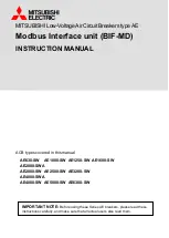
Data Flow
The data flow between CE and MPU is shown in Figure 13. In a typical application, the 32-bit compute engine (CE) sequentially
processes the samples from the inputs on pins I0 through I5, performing calculations to measure the currents for circuit breaker
operation. These measurements are then accessed by the MPU, processed further and output using the peripheral devices
available to the MPU.
CE
MPU
Pre-
Processor
Post-
Processor
IRQ
Processed
Data
I/O RAM (Configuration RAM)
Data
CE
MPU
Pre-
Processor
Post-
Processor
IRQ
Processed
Data
I/O RAM (Configuration RAM)
Data
Figure 13: MPU/CE Data Flow
CE/MPU Communication
Figure 14 shows the functional relationship between CE and MPU. The CE is controlled by the MPU via shared registers in the
I/O RAM and by registers in the CE DRAM.
Figure 15 shows the sequence of events between CE and MPU upon reset or power-up. In a typical application, the sequence of
events is as follows:
1) Upon power-up, the MPU initializes the hardware, including disabling the CE
2) The MPU loads the code for the CE into the CE PRAM
3) The MPU loads CE data into the CE DRAM.
4) The MPU starts the CE by setting the
CE_EN
bit in the I/O RAM.
5) The CE then repetitively executes its code, generating results and storing them in the CE DRAM
electronic components distributor