Section 3 ZEPHYR AT A GLANCE
40
FRONT PANEL
Display
LOCK
SYNC
RECEIVE
C H A N N E L B
SEND
2
–30
–24
–18
–12
–6
0
LEVEL
LINE
–30
–24
–18
–12
–6
0
LIMIT
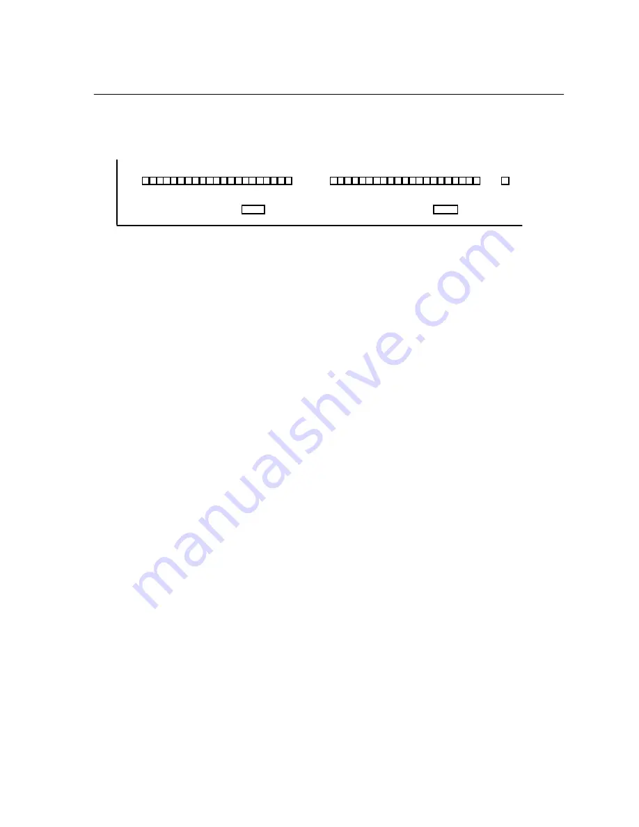
Audio Level Meters
The audio level LEDs provide a check on the send and receive audio.
The SEND audio level LED meters aid send level adjustment. Send audio should
be adjusted so that the green segments are illuminated, with the red segments flashing
occasionally. The 0 dB segment corresponds to the system clip point. However, even
this segment may illuminate without audible trouble owing to the efficacy of the
internal limiter, if engaged.
The RECEIVE audio level LEDs indicate that audio is being received and decoded. They
are calibrated to match the send audio level LEDs at the encoder.
Limit Indicators
The Zephyr has a send audio limiter which serves to keep the usual “digital nasties”
from happening when the send program signal grows instantaneously too large. This is
a very fast and very “tight” limiter which does not assert itself during times of normal
audio level. The idea here is to keep the system out of trouble when, say, a sports
announcer, on remote, gets excited.
With a sine tone, the limiter engages at 15 dB above the nominal operating value, but
since the limiter activity depends upon the peak- to- average ratio of the program
material, it may appear to operate at somewhat less than 15 dB above nominal with
some kinds of audio as input.
The LIMIT LEDs should only illuminate occasionally. If they are on consistently, reduce
the send level.
Status LEDs
The SYNC LED near the SEND meter indicates “all’s well” with the system. The software
must be loaded, up and running, and internal system clocks properly functioning. (This
LED may not always be on when you are not using the internal ISDN interface. In this
case, it reflects the status of the external interface, as well as the Zephyr’s internal
condition. Refer to manual section 6 (Non- ISDN Networks.)
The LOCK LED near the RECEIVE meter illuminates when the receive decoder has
locked on to a valid coded signal from a unit who’s transmit mode set to correspond to
your receive mode.
Summary of Contents for Zephyr
Page 13: ...Table of Contents 13 SECTION 1 QUICK RESULTS ...
Page 26: ...Section 2 INTRODUCTION 26 This page intentially left blank ...
Page 27: ...Section 2 INTRODUCTION 27 SECTION 2 INTRODUCTION ...
Page 38: ...Section 2 INTRODUCTION 38 This page intentionally left blank ...
Page 39: ...39 SECTION 3 ZEPHYR AT A GLANCE ...
Page 52: ...Section 4 INSTALLATION BASIC OPERATION 52 This page intentionally left blank ...
Page 53: ...Section 4 INSTALLATION BASIC OP 53 SECTION 4 INSTALLATION BASIC OPERATION ...
Page 84: ...Section 4 INSTALLATION BASIC OPERATION 84 ...
Page 85: ...Section 5 ISDN 85 SECTION 5 ISDN ...
Page 105: ...Section 6 NON ISDN NETWORKS 105 SECTION 7 AUDIO CODING ...
Page 118: ...Section 7 AUDIO CODING PRINCIPLES 118 This page intentionally left blank ...
Page 119: ...Section 8 DETAILED MENU REFERENCE 119 SECTION 8 DETAILED MENU REFERENCE ...
Page 157: ...Section 9 REMOTE CONTROL 157 SECTION 9 REMOTE CONTROL ...
Page 176: ...Section 9 REMOTE CONTROL 176 This page intentionally left blank ...
Page 177: ...Section 10 ADVANCED PROBLEM SOLVING 177 SECTION 10 ADVANCED PROBLEM SOLVING ...
Page 196: ...Section 10 ADVANCED PROBLEM SOLVING 196 This page intentionally left blank ...
Page 197: ...Section 11 TECHNICAL INFORMATION 197 SECTION 11 DETAILED TECHNICAL INFORMATION ...
Page 219: ...Section 12 SCHEMATICS 219 SECTION 12 SCHEMATICS ...
Page 221: ...Section 13 MANUFACTURER S DATA SHEETS 221 SECTION 13 MANUFACTURER S DATA SHEETS ...
Page 223: ...Section 14 SPECIFICATIONS WARRANTY 223 SECTION 14 SPECIFICATIONS AND WARRANTY ...
Page 228: ...228 This page intentionally left blank ...
Page 229: ...Section 15 APPENDICES 229 SECTION 15 APPENDICES ...


