


Section 11 TECHNICAL INFORMATION
207
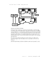
Motherboard Rev F: Send Limiter
The Zephyr has a send audio limiter which serves to keep the usual “digital nasties”
from happening when the send program signal grows instantaneously too large. This is
a very fast and a very “tight” limiter which does not assert itself during times of normal
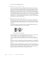
audio level. It is possible to bypass the send limiter. The blue “AGC” on the “B- audio
board” can be set to “IN” or “OUT”. “In” places the limiter in the audio path. “Out”
bypasses the entire limiter section, and the servo output is routed directly to the A/D
converter.
The limiter section has dual functions; in addition to limiting, it uses the SSM2120 (U-
23) as a VCA (voltage controlled amplifier) to implement the system “send” input
control. When the limiter is bypassed the VCA is bypassed as well and the front panel
volume- send option will no longer control input level.
Diode arrays DA1 and DA2 are clipping diodes, which prevent the A/D from ever getting
a signal which could overload it and clip offensively.
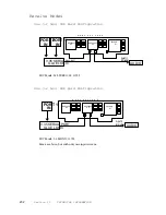
Motherboard Rev A-E: Analog-to-Digital Converter
The A/D is a single chip, stereo, 16- bit sigma- delta type converter. The A/D
oversamples the audio at 4.096 MHz. It applies noise shaping, and then filters
and decimates to a 32 kHz sampling rate. The samples are output serially and
transmitted to the XILINX chip, and ultimately to the first DSP chip in the send audio
chain.
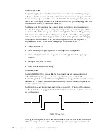
The left and right analog inputs are applied to pins 2 and 27, respectively. Pin 23
is a 4.096 MHz clock input. The divides this clock by two and outputs a 2.048 MHz clock
on pin 20. The 2.048 MHz clock is divided in the XILINX part to 32 kHz which is applied
to pin 14. Pin 16 is the data output. Both the left and right samples are to be found here,
synchronized to the 2.048 MHz bit clock. The left sample starts on the rising edge of the
clock.
Motherboard Rev F: Analog-to-Digital Converter
The Crystal Semiconductor 5390 A/D converter is a single- chip, balanced, stereo,
sigma- delta converter with 20 bit resolution. It can operate a multiple sample rates
including 16, 32, and 48 ksps as used in the Zephyr. The A- weighted SNR of the
converter is 110dB. Pin 15 is data output.
Motherboard Rev A-E: Digital-to-Analog Converter
The D/A is a single chip, stereo 18- bit D/A converter with an integral low- pass
reconstruction filter. Left and right channel audio exits the chip on pins 2 and 26,
respectively. The audio is fed to the chip in digital form on pin 18, with pin 19 being the
associated bit clock. Pin 20 is the “left/right” clock which is used to synchronize the
serial audio words. It is derived from the A/D’s pin 14 L/R clock output.
Summary of Contents for Zephyr
Page 13: ...Table of Contents 13 SECTION 1 QUICK RESULTS ...
Page 26: ...Section 2 INTRODUCTION 26 This page intentially left blank ...
Page 27: ...Section 2 INTRODUCTION 27 SECTION 2 INTRODUCTION ...
Page 38: ...Section 2 INTRODUCTION 38 This page intentionally left blank ...
Page 39: ...39 SECTION 3 ZEPHYR AT A GLANCE ...
Page 52: ...Section 4 INSTALLATION BASIC OPERATION 52 This page intentionally left blank ...
Page 53: ...Section 4 INSTALLATION BASIC OP 53 SECTION 4 INSTALLATION BASIC OPERATION ...
Page 84: ...Section 4 INSTALLATION BASIC OPERATION 84 ...
Page 85: ...Section 5 ISDN 85 SECTION 5 ISDN ...
Page 105: ...Section 6 NON ISDN NETWORKS 105 SECTION 7 AUDIO CODING ...
Page 118: ...Section 7 AUDIO CODING PRINCIPLES 118 This page intentionally left blank ...
Page 119: ...Section 8 DETAILED MENU REFERENCE 119 SECTION 8 DETAILED MENU REFERENCE ...
Page 157: ...Section 9 REMOTE CONTROL 157 SECTION 9 REMOTE CONTROL ...
Page 176: ...Section 9 REMOTE CONTROL 176 This page intentionally left blank ...
Page 177: ...Section 10 ADVANCED PROBLEM SOLVING 177 SECTION 10 ADVANCED PROBLEM SOLVING ...
Page 196: ...Section 10 ADVANCED PROBLEM SOLVING 196 This page intentionally left blank ...
Page 197: ...Section 11 TECHNICAL INFORMATION 197 SECTION 11 DETAILED TECHNICAL INFORMATION ...
Page 219: ...Section 12 SCHEMATICS 219 SECTION 12 SCHEMATICS ...
Page 221: ...Section 13 MANUFACTURER S DATA SHEETS 221 SECTION 13 MANUFACTURER S DATA SHEETS ...
Page 223: ...Section 14 SPECIFICATIONS WARRANTY 223 SECTION 14 SPECIFICATIONS AND WARRANTY ...
Page 228: ...228 This page intentionally left blank ...
Page 229: ...Section 15 APPENDICES 229 SECTION 15 APPENDICES ...


