


Section 11 TECHNICAL INFORMATION
208
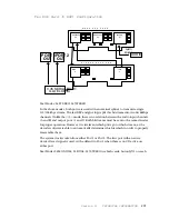
Motherboard Rev F: Digital-to-Analog Converter
Decoded audio is sent to the “B- audio board” in digital form through JA2. The
bitstream then goes to the Crystal Semiconductor 4328 D/A converter. The D/A is a
single- chip, stereo 18- bit D/A with an integral low- pass reconstruction filter. Left and
right channel audio exits the chip on pins 2 and 26 respectively. The digital audio is fed
to the chip on pin 18, with pin 19 being the associated bit clock. It is derived from the
A/D’s pin 14 L/R clock output.
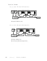
Motherboard Rev A-E: Audio Output
The analog audio signals output from the D/A pass analog switches U26C, U26D
on their way to the balanced output section. This is a shunt type switch so that it
introduces no distortion. When the switch is open, the audio passes; when the switch
closes, audio is reduced by around 40 dB owing to the voltage divider effect of the
switches and R71,72. The low- level “leakage” of audio when the switch is on is
intentional, as it allows the user to hear program at a low level when the phone audio
CODEC, U21 is allowed to pass it’s telephone audio to the system output. On the other
hand, the analog switches U26A,B, when off provide excellent isolation to prevent the
CODEC’s output from worsening the system noise. Note that the switches in the phone
CODEC path are configured series.
The output stage uses the ubiquitous NE5532 op- amps to create and present a
differential output to the XLR connectors. The output audio is passed through
L1- L4, which are PI- filters designed to prevent RF from coming into the Zephyr, and
digital clock noise from exiting. For highest quality, AC coupling happens only once in
the output path – at C35,36 – and these are electrolytic types as currently favored by
audio “tweeks.”
A very high- quality headphone amplifier is made from two LM6321 buffers and
the associated op- amp. U22 is a digitally adjusted potentiometer. Under control
of the CPU, it permits headphone gain adjustment. The digi- pot is placed in the op-
amp’s shunt feedback path, so as not to reduce headroom – the pots operate from ±
5Vdc power rails, while the audio path is only limited by the ±15 Vdc rails.
Motherboard Rev F: Audio Output
The analog audio signals output from the D/A pass analog switched U26C and U26D
(on the motherboard) on their way to the balanced output section. This is a shunt type
switch so that It introduces no distortion. When the switch is open the audio passes;
when the switch closes the audio is reduced by approximately 40 dB owing to the
voltage divider of the switch and R75 and R90. The low- level “leakage” of audio when
the switch is on is intentional as it allows the users to hear program audio at a low level
when the phone audio CODEC U21 is allowed to pass it’s telephone audio to the system
output. On the other hand, when analog switches U26A and U26B are off excellent
isolation takes place thereby preventing the phone Codec’s output from worsening
system noise. Note that the switches in the phone CODEC’s path are configured in
series. The output of the phone CODEC is only available at the analog outputs.
Summary of Contents for Zephyr
Page 13: ...Table of Contents 13 SECTION 1 QUICK RESULTS ...
Page 26: ...Section 2 INTRODUCTION 26 This page intentially left blank ...
Page 27: ...Section 2 INTRODUCTION 27 SECTION 2 INTRODUCTION ...
Page 38: ...Section 2 INTRODUCTION 38 This page intentionally left blank ...
Page 39: ...39 SECTION 3 ZEPHYR AT A GLANCE ...
Page 52: ...Section 4 INSTALLATION BASIC OPERATION 52 This page intentionally left blank ...
Page 53: ...Section 4 INSTALLATION BASIC OP 53 SECTION 4 INSTALLATION BASIC OPERATION ...
Page 84: ...Section 4 INSTALLATION BASIC OPERATION 84 ...
Page 85: ...Section 5 ISDN 85 SECTION 5 ISDN ...
Page 105: ...Section 6 NON ISDN NETWORKS 105 SECTION 7 AUDIO CODING ...
Page 118: ...Section 7 AUDIO CODING PRINCIPLES 118 This page intentionally left blank ...
Page 119: ...Section 8 DETAILED MENU REFERENCE 119 SECTION 8 DETAILED MENU REFERENCE ...
Page 157: ...Section 9 REMOTE CONTROL 157 SECTION 9 REMOTE CONTROL ...
Page 176: ...Section 9 REMOTE CONTROL 176 This page intentionally left blank ...
Page 177: ...Section 10 ADVANCED PROBLEM SOLVING 177 SECTION 10 ADVANCED PROBLEM SOLVING ...
Page 196: ...Section 10 ADVANCED PROBLEM SOLVING 196 This page intentionally left blank ...
Page 197: ...Section 11 TECHNICAL INFORMATION 197 SECTION 11 DETAILED TECHNICAL INFORMATION ...
Page 219: ...Section 12 SCHEMATICS 219 SECTION 12 SCHEMATICS ...
Page 221: ...Section 13 MANUFACTURER S DATA SHEETS 221 SECTION 13 MANUFACTURER S DATA SHEETS ...
Page 223: ...Section 14 SPECIFICATIONS WARRANTY 223 SECTION 14 SPECIFICATIONS AND WARRANTY ...
Page 228: ...228 This page intentionally left blank ...
Page 229: ...Section 15 APPENDICES 229 SECTION 15 APPENDICES ...


