


Section 11 TECHNICAL INFORMATION
203
GAINING ACCESS
The installation and servicing instructions in this manual are for use by
qualified personnel only. To avoid electric shock do not perform any ser-
vicing other than that contained in the Operating Instructions unles s you
are qualified to do so. Refer all servicing to qualified service personnel.
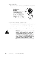
CAUTION
CAUTION: As with most switching power supplies the Zephyr’s power supply has lethal
voltages, even on parts which might look safe at casual glance.
DO NOT TOUCH ANY
PORTION OF THE POWER SUPPLY without removing power cord first
.
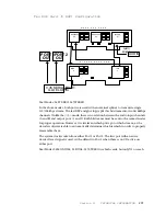
Removal of the top plate is the first step to gaining access for service. Remove the ten
Philips head screws.
Motherboard Removal
REALLY IMPORTANT NOTE!!
In the case where it is necessary to remove the motherboard,
remove the two screws which mount each of the cards to the
rear panel, remove the retainer screws on the lower DB
connectors, remove the *4* screws which hold the board
down (There is one hiding at the rear end of P2!), and then
release the XLR connectors according to the instructions
below. Disconnect all cables, and away you go.
Summary of Contents for Zephyr
Page 13: ...Table of Contents 13 SECTION 1 QUICK RESULTS ...
Page 26: ...Section 2 INTRODUCTION 26 This page intentially left blank ...
Page 27: ...Section 2 INTRODUCTION 27 SECTION 2 INTRODUCTION ...
Page 38: ...Section 2 INTRODUCTION 38 This page intentionally left blank ...
Page 39: ...39 SECTION 3 ZEPHYR AT A GLANCE ...
Page 52: ...Section 4 INSTALLATION BASIC OPERATION 52 This page intentionally left blank ...
Page 53: ...Section 4 INSTALLATION BASIC OP 53 SECTION 4 INSTALLATION BASIC OPERATION ...
Page 84: ...Section 4 INSTALLATION BASIC OPERATION 84 ...
Page 85: ...Section 5 ISDN 85 SECTION 5 ISDN ...
Page 105: ...Section 6 NON ISDN NETWORKS 105 SECTION 7 AUDIO CODING ...
Page 118: ...Section 7 AUDIO CODING PRINCIPLES 118 This page intentionally left blank ...
Page 119: ...Section 8 DETAILED MENU REFERENCE 119 SECTION 8 DETAILED MENU REFERENCE ...
Page 157: ...Section 9 REMOTE CONTROL 157 SECTION 9 REMOTE CONTROL ...
Page 176: ...Section 9 REMOTE CONTROL 176 This page intentionally left blank ...
Page 177: ...Section 10 ADVANCED PROBLEM SOLVING 177 SECTION 10 ADVANCED PROBLEM SOLVING ...
Page 196: ...Section 10 ADVANCED PROBLEM SOLVING 196 This page intentionally left blank ...
Page 197: ...Section 11 TECHNICAL INFORMATION 197 SECTION 11 DETAILED TECHNICAL INFORMATION ...
Page 219: ...Section 12 SCHEMATICS 219 SECTION 12 SCHEMATICS ...
Page 221: ...Section 13 MANUFACTURER S DATA SHEETS 221 SECTION 13 MANUFACTURER S DATA SHEETS ...
Page 223: ...Section 14 SPECIFICATIONS WARRANTY 223 SECTION 14 SPECIFICATIONS AND WARRANTY ...
Page 228: ...228 This page intentionally left blank ...
Page 229: ...Section 15 APPENDICES 229 SECTION 15 APPENDICES ...


