Operating
Instructions
—DM 5010
5
CAUTION <
To avoid
equipment damage,
do not apply a voltage
exceeding 42.4 V peak ac or 60 V de between pins
28B (Hi)
and 28A (Lo) of the rear-interface connector
P1031 on
the
ADC board (A
17).
>
CAUTION <
cathode
to the LOW. Devices that
can
be checked are those
having a voltage drop
under 1.999 volts. These include most
diodes
and some
LEDs.
To check the reverse
voltage drop,
reverse the diode
connections to the instrument.
The display window should
display OC.
Do
not
switch from front-pane! to rear interface input
while
over 500 V peak is appiied
to the
front panei
input connectors.
Instrument damage and erratic op
eration may result.
DC
Voltage
Measurements
When
the DCV button is pressed, the DM 5010 mea
sures
dc voltages
using the following ranges:
200 mV,
2
V,
20
V, 200
V, and 1000 V.
The readout displays a positive
sign
when
the
input to the HIGH connector is
positive with
respect to
the LOW
connector. Observe the maximum input
voltage
ratings.
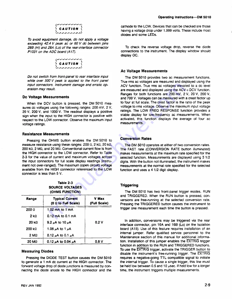
Resistance
Measurements
Pressing
the OHMS button enables the DM5010 to
measure resistance
using these ranges: 200
Ω, 2 kΩ, 20 kΩ,
200
kΩ, 2 MΩ, and 20 MΩ. Conventional current flow is from
the
HIGH
connector to the LOW connector.
Refer to Table
2-3 for the value of current and maximum voltages across
the
input connectors for
full
scale display readings (instru
ment not over-ranged). The maximum
(open circuit) voltage
available from
the
HIGH
connector referenced to the LOW
connector is less
than 5
V.
Ac
Voltage
Measurements
The
DM 5010 provides two ac measurement functions.
True
rms
ac voltages
are measured and displayed using
the
ACV function.
True rms ac voltages
elevated to a dc
level
are measured and
displayed using the
ACV+DCV function.
Ranges
for
both functions are 200 mV, 2 V, 20 V, 200 V,
and
700 V.
Voltages can be measured with a crest factor
up
to
four at full scale. The crest factor is the ratio of the peak
voltage to rms voltage.
Observe the maximum input voltage
ratings.
The LOW FREQ RESPONSE function provides a
stable
display for low-frequency ac measurements. When
activated, this
function
displays the average
of
four
ac
measurements.
Conversion
Rates
The DM 5010 operates at either of two
conversion rates.
The FAST
rate (CONVERSION RATE button illuminated)
makes
measurements at the maximum
rate specified for the
selected
function.
Measurements are displayed using 3 1/2
digits. With
the
button not illuminated, the
instrument makes
measurements
at the normal
rate specified for the selected
function
and uses a 4 1/2 digit display.
Table
2-3
SOURCE VOLTAGES
(OHMS
FUNCTION)
Range
Typical Current
(0
Ω
to Full
Scale)
V
Max
(Full
Scale)
200
Ω
1.02 mA to 1 mA
2
kΩ
0.12 mA to 0.1
mA
20
kΩ
9.2 µA to 10 µA
0.2 V
200 kΩ
1.08
µA to 1
µA
2 MΩ
0.12 µA to 0.1 µA
20
MΩ
0.12
µA
to 0.04 µA
0.8 V
Measuring Diodes
Pressing the DIODE TEST button causes the DM 5010
to
generate
a
1 mA dc current at the HIGH connector. The
forward voltage
drop of diode junctions is measured by con
necting the
diode anode to the HIGH connector and the
Triggering
The
DM 5010 has two front-panel trigger modes, RUN
and
TRIGGERED.
When the RUN button is pressed, con
versions are
free-running
at the selected conversion rate.
Pressing the TRIGGERED button causes the instrument
to
trigger
one measurement
each time the button is pressed.
In addition, conversions
may be triggered via the rear
interface connector, pin
16A and 16B (Lo) on the Isolation
board
(A15).
Use of this feature requires installation of an
internal
jumper. Refer qualified service personnel to the
Maintenance
section
of this manual for additional informa-
tion. Installation
of this jumper enables the EXTRIG
trigger
function
in addition to the RUN and TRIGGERED functions.
To use the EXTRIG trigger, activate the TRIGGER button to
disable
the
instrument’s free-running trigger. The EXTRIG
requires a negative-going TTL compatible signal to initiate
the
internal trigger. To cause a single trigger, this line must
be
held low between 0.5 and 10 µsec. If held low for a longer
time, the
instrument triggers multiple measurements.
REV
JAN
1982
2-9
Summary of Contents for DM 5010
Page 14: ...DM 5010 2994 00 DM 5010 Programmable Digital Multimeter xii ADD JUL 1986...
Page 27: ...Operating Instructions DM 5010 2994 03 Fig 2 3 DM 5010 front panel controls and connectors 2 3...
Page 38: ......
Page 134: ......
Page 208: ......
Page 222: ......
Page 250: ......
Page 251: ...Section 8 DM 5010 OPTIONS No options are available 8 1...
Page 252: ......
Page 270: ......
Page 272: ...DM 5010 2994 37 Fig 10 2 Location of DM 5010 adjustments and test points...
Page 273: ......
Page 274: ......
Page 275: ......
Page 276: ...DM 5010 2994 112 DM 5010 BLOCK DIAGRAM...
Page 281: ......
Page 282: ......
Page 291: ......
Page 293: ......
Page 294: ......
Page 297: ......
Page 298: ......
Page 303: ......
Page 304: ...I...
Page 305: ......
Page 310: ......
Page 311: ......
Page 315: ......
Page 318: ......
Page 321: ......
Page 323: ......
Page 326: ......
Page 332: ...2994 57...
Page 334: ......
Page 335: ......
Page 336: ......
Page 337: ...63 REV JUN 1986...
Page 338: ...FIG 1 EXPLODED DM 5010...
Page 339: ......
Page 340: ......
Page 341: ......
Page 347: ......