


Maintenance
—DM 5010
Table
7-3
(cont)
Typical
Symptoms
Circuit Section—
Verification
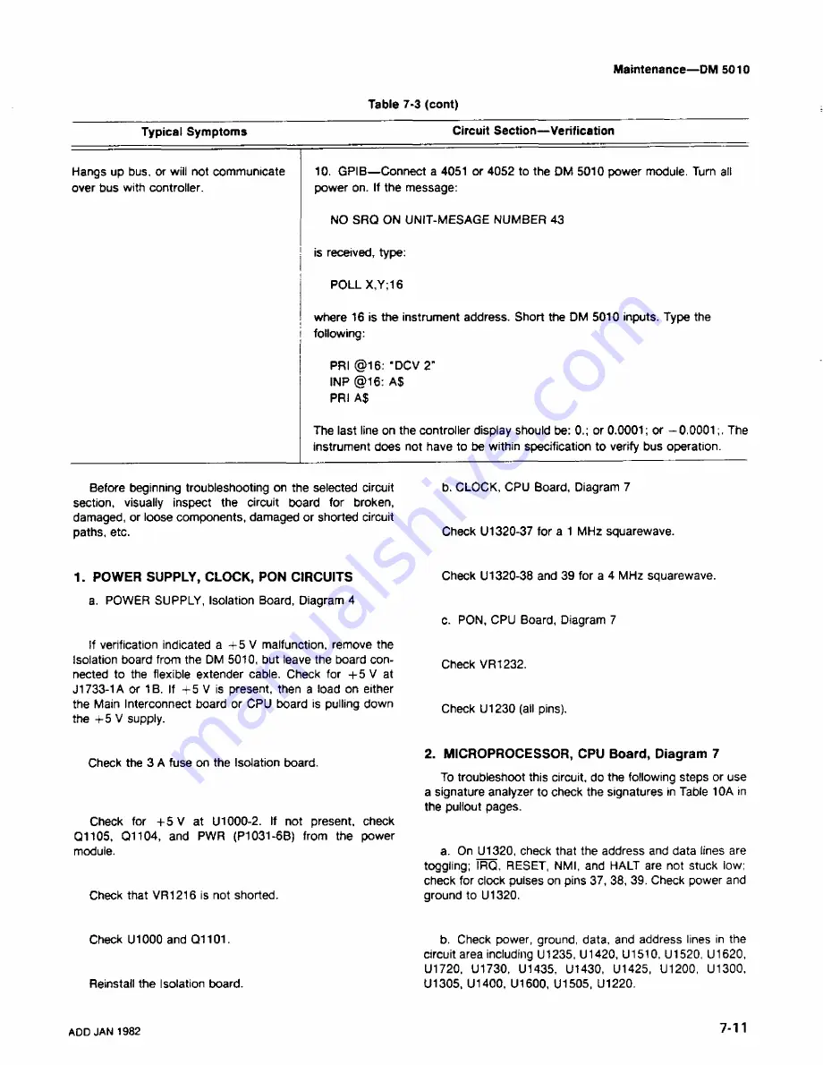
Hangs
up bus, or will not
communicate
over
bus with
controller.
10.
GPIB—Connect a 4051
or 4052 to the DM 5010 power module. Turn all
power on.
If the message:
NO
SRQ
ON UNIT-MESAGE NUMBER
43
is received, type:
POLL X,Y;16
where 16
is the instrument
address. Short the DM 5010 inputs. Type the
following:
PRI
@16:
‘DCV 2"
INP @16: AS
PRI
A$
The last
line on the controller display should be: 0.; or 0.0001; or —0.0001;. The
instrument
does not
have to
be within specification to verify bus operation.
Before
beginning troubleshooting on the selected circuit
section,
visually
inspect the circuit board for broken,
damaged,
or
loose
components,
damaged or shorted circuit
paths,
etc.
1.
POWER
SUPPLY, CLOCK, PON CIRCUITS
a. POWER SUPPLY, Isolation Board, Diagram 4
If
verification
indicated a
+5V malfunction, remove the
Isolation board
from the DM 5010, but leave the
board con
nected to
the flexible extender cable. Check for +5 V at
J1733-1A
or
1B. If +5 V is present, then a load on either
the
Main Interconnect
board or CPU board is pulling down
the
4-5 V supply.
Check
the 3 A
fuse on the Isolation board.
Check
for 4-5 V at U1000-2. If not present, check
Q1105, Q1104, and
PWR
(P1031-6B) from the power
module.
Check that
VR1216 is not shorted.
b. CLOCK, CPU Board,
Diagram 7
Check U1320-37 for a 1 MHz squarewave.
Check U1320-38
and 39 for a 4 MHz squarewave.
c.
PON, CPU
Board, Diagram 7
Check
VR1232.
Check
U1230 (all pins).
2.
MICROPROCESSOR, CPU
Board, Diagram 7
To
troubleshoot this circuit, do the following steps or
use
a signature analyzer to check the signatures in
Table 10A in
the
pullout pages.
a. On U1320, check that the address and data lines are
toggling; IRQ, RESET, NMI,
and HALT are not stuck iow;
check
for clock pulses on
pins 37, 38, 39. Check power and
ground
to
U1320.
Check U1000
and
Q1101.
Reinstall
the Isolation board.
b. Check power, ground, data, and
address lines
in the
circuit
area including U1235, U1420, U1510, U1520,
U1620,
U1720, U1730,
U1435, U1430, U1425, U1200, U1300,
U1305, U1400,
U1600,
U1505,
U1220.
ADD JAN
1982
7-11
Summary of Contents for DM 5010
Page 14: ...DM 5010 2994 00 DM 5010 Programmable Digital Multimeter xii ADD JUL 1986...
Page 27: ...Operating Instructions DM 5010 2994 03 Fig 2 3 DM 5010 front panel controls and connectors 2 3...
Page 38: ......
Page 134: ......
Page 208: ......
Page 222: ......
Page 250: ......
Page 251: ...Section 8 DM 5010 OPTIONS No options are available 8 1...
Page 252: ......
Page 270: ......
Page 272: ...DM 5010 2994 37 Fig 10 2 Location of DM 5010 adjustments and test points...
Page 273: ......
Page 274: ......
Page 275: ......
Page 276: ...DM 5010 2994 112 DM 5010 BLOCK DIAGRAM...
Page 281: ......
Page 282: ......
Page 291: ......
Page 293: ......
Page 294: ......
Page 297: ......
Page 298: ......
Page 303: ......
Page 304: ...I...
Page 305: ......
Page 310: ......
Page 311: ......
Page 315: ......
Page 318: ......
Page 321: ......
Page 323: ......
Page 326: ......
Page 332: ...2994 57...
Page 334: ......
Page 335: ......
Page 336: ......
Page 337: ...63 REV JUN 1986...
Page 338: ...FIG 1 EXPLODED DM 5010...
Page 339: ......
Page 340: ......
Page 341: ......
Page 347: ......


