


Instructions d'utilisation
* DM 5010
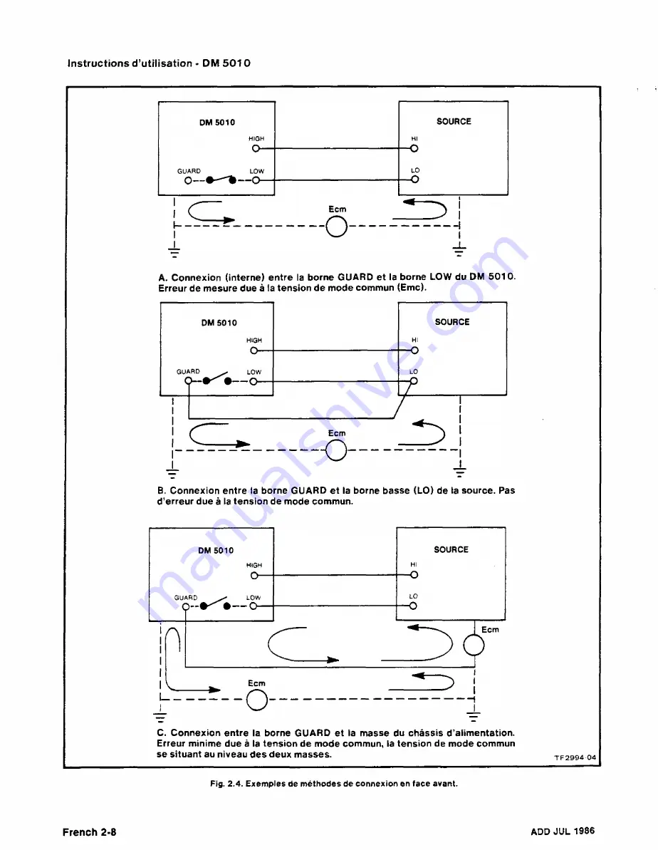
A.
Connexion
(interne) entre la borne GUARD et la borne LOW du DM 5010.
Erreur
de
mesure due à
la tension de mode commun (Emc).
B. Connexion entre
la borne GUARD et la borne basse (LO) de la source. Pas
d
’erreur
due
à
la tension de mode commun.
C.
Connexion entre
la borne
GUARD et la masse du châssis d’alimentation.
Erreur
minime
due à
la tension de mode commun, la tension de mode commun
se situant au niveau des deux masses.
Fig. 2.4. Exemples de méthodes de connexion en
face
avant.
French
2-8
ADD
JUL 1986
Summary of Contents for DM 5010
Page 14: ...DM 5010 2994 00 DM 5010 Programmable Digital Multimeter xii ADD JUL 1986...
Page 27: ...Operating Instructions DM 5010 2994 03 Fig 2 3 DM 5010 front panel controls and connectors 2 3...
Page 38: ......
Page 134: ......
Page 208: ......
Page 222: ......
Page 250: ......
Page 251: ...Section 8 DM 5010 OPTIONS No options are available 8 1...
Page 252: ......
Page 270: ......
Page 272: ...DM 5010 2994 37 Fig 10 2 Location of DM 5010 adjustments and test points...
Page 273: ......
Page 274: ......
Page 275: ......
Page 276: ...DM 5010 2994 112 DM 5010 BLOCK DIAGRAM...
Page 281: ......
Page 282: ......
Page 291: ......
Page 293: ......
Page 294: ......
Page 297: ......
Page 298: ......
Page 303: ......
Page 304: ...I...
Page 305: ......
Page 310: ......
Page 311: ......
Page 315: ......
Page 318: ......
Page 321: ......
Page 323: ......
Page 326: ......
Page 332: ...2994 57...
Page 334: ......
Page 335: ......
Page 336: ......
Page 337: ...63 REV JUN 1986...
Page 338: ...FIG 1 EXPLODED DM 5010...
Page 339: ......
Page 340: ......
Page 341: ......
Page 347: ......


