


Performance Check—
DM 5010
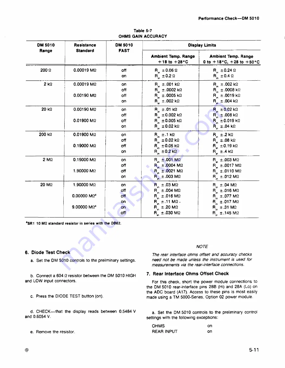
Table
5-7
OHMS
GAIN ACCURACY
DM
5010
Range
Resistance
Standard
DM 5010
FAST
Display Limits
Ambient Temp. Range
4-18
to
4-28’C
Ambient
Temp. Range
0 to
4-18’C, 4-28 to
4-50°C
200
Ω
0.00019 MΩ
off
R|n
±0.06Ω
R
m
±0.24
Ω
I
on
Rin
±0.2 Ω
in
R
±0.4Ω
m
2 kΩ
0.00019 MΩ
on
R,n
±.001
kΩ
R^
±
.002 kΩ
off
± .0002 kΩ
R
p
± .0008 kΩ
0.00190
MΩ
off
± .0005 kΩ
on
R
±
.002 kΩ
tn
R
±
.004 kΩ
in
20
kΩ
0.00190
MΩ
on
R
in
± .01
kΩ
R|n
±0.02 kΩ
off
R
* ±0.002
kΩ
r
"
±
.008 kΩ
0.01900 MΩ
off
r
"
±0.005 kΩ
R|n
±0.019 kΩ
on
R
±0.02kΩ
m
R ±.04 kΩ
in
200 kΩ
0.01900 MΩ
on
R|n ±.1
kΩ
R|n ±
.2 kΩ
off
R^
±0.02 kΩ
R^
± .08 kΩ
0.19000
MΩ
off
R>n
±0.05 kΩ
R
m
±0.19 kΩ
on
R ±0.2 kΩ
n
R
±
,4 kΩ
tn
2 MΩ
0.19000 MΩ
on
R
r
± .001 MΩ
R^
± .003 MΩ
off
Rr ± .0004 MΩ
r
"
±.0017 MΩ
1.90000
MΩ
off
R"
± .0021 MΩ
R"
±.0110 MΩ
on
R
±
.003 MΩ
tn
R°
±.012
MΩ
in
20
MΩ
1.90000 MΩ
on
R|n
± .03 MΩ
R|n ± .04
MΩ
off
r
"
± .004 MΩ
R^
±.016
MΩ
0.00000
MΩa
off
R
in ±.016 MΩ
r
"
± .077 MΩ
on
R.n ±.11 MΩ -
R|n
±.017 MΩ
9.00000
MΩ
a
on
r
"
± .20 MΩ
R"
±.31 MΩ
off
R
1
" ± .030 MΩ
Rlfl ±.145 MΩ
tn
in
8SR1
10 MΩ standard resistor in series with the DB62.
6.
Diode Test
Check
a. Set the DM 5010 controls to the preliminary settings.
b. Connect a 604 Ω resistor between the DM 5010 HIGH
and
LOW
input
connectors.
c.
Press the DIODE TEST
button (on).
d.
CHECK—
that
the display reads between 0.5484 V
and
0.6054 V.
NOTE
The
rear interface ohms
offset and accuracy checks
need not be
made unless
the instrument is used for
measurements
via the rear-interface connections.
7.
Rear
Interface Ohms Offset Check
For this check,
short the power module connections to
the
DM 5010 rear-interface pins 28B (Hi) and 28A (Lo) on
the
ADC board (A17).
Access to these pins is most easily
made using
a TM 5000-Series, Option 02 power module.
a. Set the
DM 5010 controls to the preliminary control
settings
with the following exceptions:
e. Remove the resistor.
OHMS
REAR
INPUT
on
on
5
11
Summary of Contents for DM 5010
Page 14: ...DM 5010 2994 00 DM 5010 Programmable Digital Multimeter xii ADD JUL 1986...
Page 27: ...Operating Instructions DM 5010 2994 03 Fig 2 3 DM 5010 front panel controls and connectors 2 3...
Page 38: ......
Page 134: ......
Page 208: ......
Page 222: ......
Page 250: ......
Page 251: ...Section 8 DM 5010 OPTIONS No options are available 8 1...
Page 252: ......
Page 270: ......
Page 272: ...DM 5010 2994 37 Fig 10 2 Location of DM 5010 adjustments and test points...
Page 273: ......
Page 274: ......
Page 275: ......
Page 276: ...DM 5010 2994 112 DM 5010 BLOCK DIAGRAM...
Page 281: ......
Page 282: ......
Page 291: ......
Page 293: ......
Page 294: ......
Page 297: ......
Page 298: ......
Page 303: ......
Page 304: ...I...
Page 305: ......
Page 310: ......
Page 311: ......
Page 315: ......
Page 318: ......
Page 321: ......
Page 323: ......
Page 326: ......
Page 332: ...2994 57...
Page 334: ......
Page 335: ......
Page 336: ......
Page 337: ...63 REV JUN 1986...
Page 338: ...FIG 1 EXPLODED DM 5010...
Page 339: ......
Page 340: ......
Page 341: ......
Page 347: ......


