


Bedienungsanleitung
- DM 5010
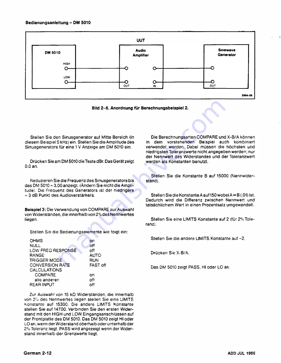
Bild
2-6.
Anordnung
für Berechnungsbeispiel 2.
Stellen Sie
den Sinusgenerator
auf Mitte Bereich (in
diesem Beispiel
5 kHz) ein.
Stellen Sie die Amplitude des
Sinusgenerators
für eine 1 V Anzeige am
DM 5010 ein.
Drücken
Sie am DM
5010
die
Taste dBr. Das Gerät zeigt
0.0
an.
Reduzieren Sie die Frequenz des Sinusgenerators bis
das DM
5010
- 3.00 anzeigt. (Ändern Sie nicht die Ampli
tude).
Die Frequenz des Generators ist der niedrigere
- 3 dB Punkt des Audioverstärkers.
Beispiel 3:
Die
Verwendung von COMPARE zur Auswahl
von
Widerständen, die innerhalb
von 2%des
Nennwertes
liegen.
Stellen Sie die Bedienungseiemente wie folgt ein:
OHMS
on
NULL
off
LOW
FREQ RESPONSE
off
RANGE
AUTO
TRIGGER
MODE
RUN
CONVERSION RATE
FAST off
CALCULATIONS
COMPARE
on
alie anderen
off
REAR
INPUT
off
Die Berechnungsarten COMPARE und X-B/A können
in
dem vorstehenden Beispiel auch kombiniert
verwendet werden. Dabei müssen die
höchsten und
niedrigsten
Toleranzwerte nicht angegeben werden;
nur
der
Nennwert des Widerstandes
und der Toleranzwert
werden
als
Konstanten benutzt.
Stellen
Sie
die
Konstante B auf 15000 (Nennwider
stand).
Stellen
Sie die
KonstanteAauf150wobeiA = B(.
01)
ist.
Dadurch wird
die Differenz zwischen Nennwert
und
tatsächlichem
Wert in einen Prozentsatz umgewandelt.
Stellen Sie eine LIMITS Konstante auf 2 (für 2% Tole
ranz) .
Stellen Sie
die andere LIMITS Konstante auf -2.
Drücken Sie
X-B/A.
Das DM 5010
zeigt
PASS, Hl oder LO an.
Zur Auswahl
von 15 kΩ Widerständen, die innerhalb
von 2% des Nennwertes liegen stellen Sie eine
LIMITS
Konstante auf
15300. Die andere LIMITS Konstante
stellen Sie
auf 14700. Verbinden Sie den ersten Wider
stand mit den HIGH und LOW
Eingangsanschlüssen auf
der
Frontplatte
des
DM 5010. Das DM
5010 zeigt
Hl oder
LO
an, wenn
der Widerstand oberhalb oder unterhalb der
2%
Toleranz
liegt.
PASS
wird angezeigt wenn der Wider
stand innerhalb der Grenzwerte
liegt.
German 2-12
ADD
JUL
1986
Summary of Contents for DM 5010
Page 14: ...DM 5010 2994 00 DM 5010 Programmable Digital Multimeter xii ADD JUL 1986...
Page 27: ...Operating Instructions DM 5010 2994 03 Fig 2 3 DM 5010 front panel controls and connectors 2 3...
Page 38: ......
Page 134: ......
Page 208: ......
Page 222: ......
Page 250: ......
Page 251: ...Section 8 DM 5010 OPTIONS No options are available 8 1...
Page 252: ......
Page 270: ......
Page 272: ...DM 5010 2994 37 Fig 10 2 Location of DM 5010 adjustments and test points...
Page 273: ......
Page 274: ......
Page 275: ......
Page 276: ...DM 5010 2994 112 DM 5010 BLOCK DIAGRAM...
Page 281: ......
Page 282: ......
Page 291: ......
Page 293: ......
Page 294: ......
Page 297: ......
Page 298: ......
Page 303: ......
Page 304: ...I...
Page 305: ......
Page 310: ......
Page 311: ......
Page 315: ......
Page 318: ......
Page 321: ......
Page 323: ......
Page 326: ......
Page 332: ...2994 57...
Page 334: ......
Page 335: ......
Page 336: ......
Page 337: ...63 REV JUN 1986...
Page 338: ...FIG 1 EXPLODED DM 5010...
Page 339: ......
Page 340: ......
Page 341: ......
Page 347: ......


