background image


41 

  SV 200A User Manual 

5.1.2  Configuration Menu 


The  instrument  control  panel  enables  limited  tools  for  configuration  the 
instrument and measurements. The configuration can be performed through 

the instrument’s 

Menu

, which is opened by simultaneous pressing of the 


and


keys and consists of several configuration sections: 


Function

, which enables selecting of the measurement function or 

performing calibration; 


Measurement

, which enables configuring measurements, 


Display

,  which  enables  configuring  automatic  switching  off  the 

screen; 


Instrument

,  which  enables  configuring 

the  instrument’s  real-time 

clock and viewing instrument’s serial number and firmware version; 


Auxiliary Setup

, which enables selecting of the interface language 

and recovering factory settings. 

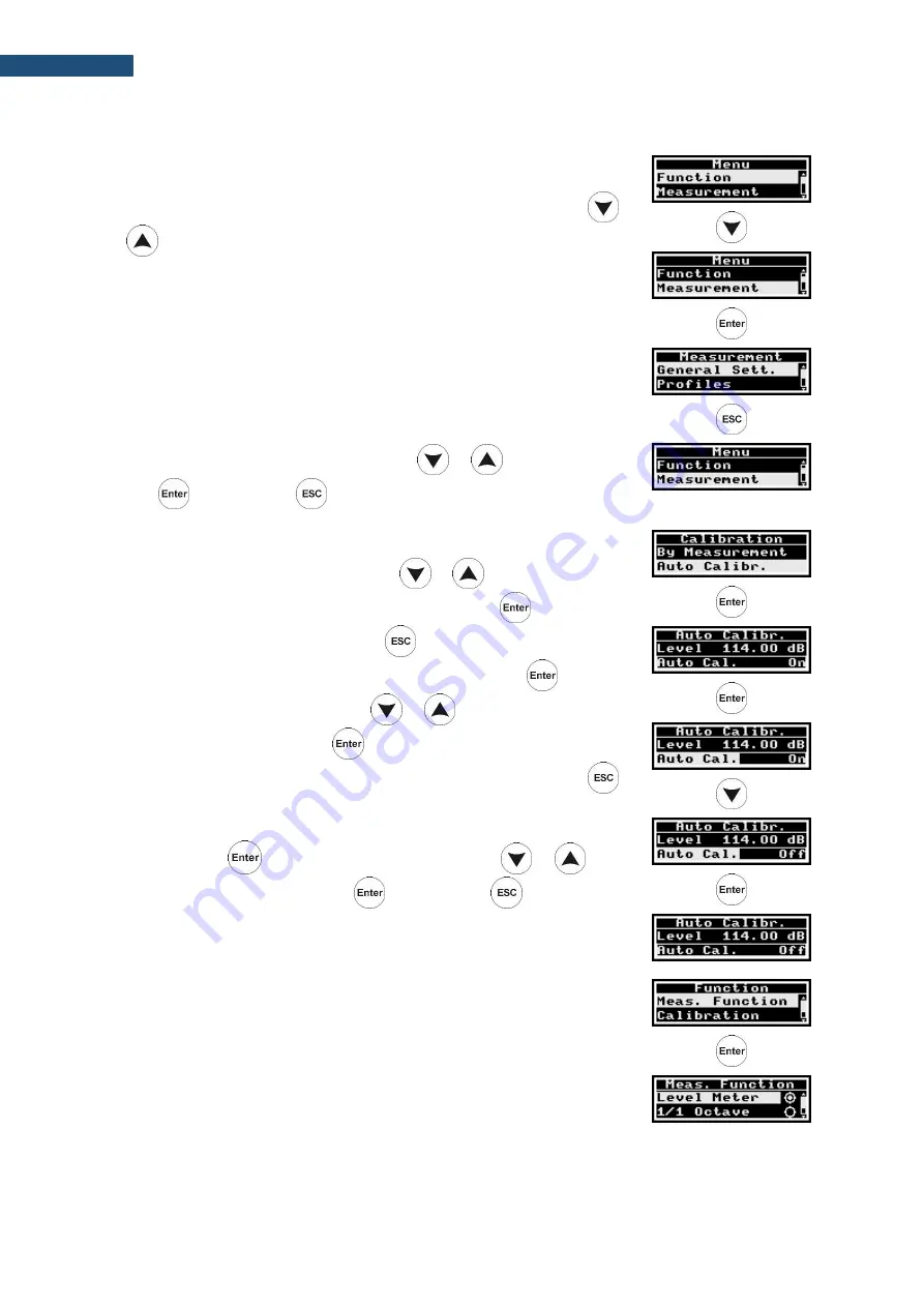
The required section can be selected with the 


or


key and opened 

with the  

 key. Using the 

 key you can exit the current section. 


In the 

Menu

 screens, you can: 


select the required position with the 


or


key, 


open new screen of the selected position with the  

 key, 


return to the upper menu with the 

 key, 


make selected parameter ready for changing with the  

 key, 


select parameter value with the 


or


key, 


confirm changes with the  

 key, 


exit  the  current  screen  with  parameters  unchanged  with  the   


key. 

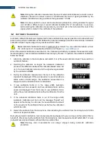
For  example,  to  switch  auto  calibration,  you  should  select  the 

Auto Cal.


position, press the 

 key and select 

On

 or 

Off

 with the 


or


key. 

To  confirm  the  selection,  press 

,  and  press 

  to  exit  the 

Auto Calibration

 screen. 


Function

 section contains positions: 


Measurement Function

which 

enables 

selecting 

of 

the 

measurement function: 

Level Meter

1/1 Octave

 or 

1/3 Octave


Summary of Contents for SV 200A

Page 1: ...USER MANUAL SV 200A NOISE MONITORING STATION Warsaw 2019 07 02 Rev 1 05 Copyright 2019 SVANTEK All rights reserved ...

Page 2: ...tered trademarks of Microsoft Corporation The Bluetooth 1 word mark and logos are registered trademarks owned by Bluetooth SIG Inc Disclaimer Information in this document is subject to change without notice and does not represent a commitment on the part of Svantek Svantek provides this document as is without warranty of any kind either expressed or implied including but not limited to its particu...

Page 3: ...rtation and storage or other operations with the instrument like laboratory calibration etc to avoid personal injury Tripod or pole with 3 8 thread is not recommended for permanent installation The windscreen influences the free field characteristics of the instrument therefore it is important to check its condition regularly In the case of visible degradation of the foam surface it must be replac...

Page 4: ... 17 2 4 Mounting 21 2 4 1 Mounting SV 200A on the mast 21 2 4 2 Mounting on 3 8 thread 24 2 4 3 Mounting the SV200A station on the mast aligning to the North 24 2 5 Anti theft protection 25 2 6 Windscreen protection 25 2 7 Power supply unit 25 2 8 Assembling the SP 275 weather station on the mast optionally 26 2 9 Finishing 26 3 SV 200A CONNECTORS AND CONTROL PANELS 27 3 1 Connectors panel 27 3 1 ...

Page 5: ... 6 5 Interface capabilities of Bluetooth module 48 7 CONFIGURATION OF THE REMOTE CONNECTION SVANNET APP 49 7 1 Configuration of the SV 200A connections 50 7 1 1 Remote Communication Settings 51 7 2 SV 200A System Check 53 7 3 Icons of SVANNET APP 53 7 4 Advanced Mode 54 7 5 Other options 55 8 SVANNET WEB SERVICE 56 8 1 Station list view 56 8 1 1 STATUS view 58 8 1 2 LOG views 60 8 2 WEB INTERFACE ...

Page 6: ... Remote Communication Service 106 9 9 3 SVAN Files 107 9 9 4 Automatic Files Downloading 109 9 9 5 Continuous Logger Download 112 9 9 6 Live Results 114 9 9 7 Alarms 116 10 NOISE SOURCE DIRECTION DETERMINATION 117 11 INSTRUMENT UPGRADE 119 11 1 Instrument upgrade via USB cable 119 11 2 Firmware upgrade via SvanNET Web service 119 12 MAINTENANCE 121 12 1 Transportation and storage 121 12 2 Cleaning...

Page 7: ...Record with GPS data 144 B 3 Structure of the CSV file 145 B 4 Structure of the SVT file 145 B 5 Structure of the SVA file 145 B 6 Structure of the TXT file 145 B 7 Structure of the LOG file 145 B 8 Date and time 145 Appendix C TECHNICAL SPECIFICATIONS 146 C 1 Specification of SV 200A in the standard configuration 146 C 2 Specification of the SV 200A 1 1 and 1 3 OCTAVE analysis 174 C 3 Frequency c...

Page 8: ... 34 35 42 76 98 Calibration factor 33 34 35 Calibration level 33 34 Channels 89 Charging 39 CLD 112 Communication 40 Compensation Filter 44 Con nozzle 30 Configuration 66 Connection status 40 Connector panel 27 Continuous trigger 93 Control keys 29 Control panel 28 38 CSV export 68 93 D Data transfer log 60 DC IN 27 Deleting files 109 Detector 43 66 90 Display 28 44 Downloading files 108 E E mail ...

Page 9: ...rophone protective sleeve 15 30 32 Mobile Network 51 MULT I O 28 O Outdoor filter 89 P Power supply 25 27 Power Supply view 40 Pre assembling 17 Profiles 43 89 Project name 78 Protective cup 17 R Recording trigger 93 Recording type 92 Remote communication 96 Remote Communication Center 80 Remote Connection Wizard 82 Remote control 45 46 Repetition cycles 43 89 Reset 121 RMS Integration 66 89 RTC 4...

Page 10: ...tion 97 Traffic 40 U Unit Label 45 Updating RTC 109 Upgrading 119 Uploading files 108 USB 44 V Vertical view 39 View mode 38 W Wave 70 Wave recording 92 Weather station 14 26 Windscreen 19 25 30 Wireless 44 WLAN 44 48 WLAN Access Point 54 55 WLAN Infrastructure 51 Working directory 85 ...

Page 11: ...tion option for the SvanPC software and the SvanNET web server provides advanced communication with files downloading data visualization and measurement results exporting Environmental monitoring option for the SvanPC software is dedicated for measurement data management advanced data processing analysis visualization and reporting Thanks to robust casing protection against overheating humidity co...

Page 12: ...ition of the instrument Up to 6 days of autonomy operation internal battery operating time with all radio modules off Advanced software for data processing and reporting SvanPC _EM Li Ion 72 4 Wh rechargeable battery non removable Direct connection of solar panel without controller or DC power supply Robust design Ingress Protection Rating IP 65 Easy and fast installation in field Directivity of d...

Page 13: ...es an acoustic pressure of defined level 94 114 dB at a frequency of 1 kHz 1 4 2 SB 276 solar panel The SB 276 solar panel 40 W 17 5 V extends the working time of the monitoring station Size and weight of the panel enables easy transportation in the dedicated carrying bag SB 276 does not require additional batteries or external controllers SB 276 is equipped with a military standard connector cabl...

Page 14: ...ed and direction are transferred from the SP 275 to the monitoring station every second Precipitation and 3 values for rain and hail intensity accumulation and duration are transferred every 10 seconds only when it is raining or hailing SV 200A may save them in the logger file as a Summary Results with the Integration Period step and as a time history results with the Logger Step see Chapters 9 8 ...

Page 15: ...lient consists of the following elements 1 the SV 200A instrument includes next permanently integrated elements integrated non removable microphone preamplifier built in electrostatic actuator triggered manually or in automatic mode Li Ion rechargeable battery 16 GB micro SD card 3G modem WLAN module Bluetooth module eCompass sensor GPS receiver control panel 4 x MEMS microphones 2 and elements th...

Page 16: ...m Allen key 5mm 6 DC power supply kit weatherproof DC power unit of the type SB 274 set of 4 dowels Φ 10 mm with screws for mounting the power unit onto a wall 2 band clips for mounting of the power supply on a mast The instrument kit is delivered in the special case which is dedicated also for storage and transportation of the instrument base of the sleeve M14 3 8 adapter with two bolts M6x12 wit...

Page 17: ...e protective cap from the microphone socket 4 Holding outer cone in one hand use the other hand to screw the microphone on the matching thread extending from the outer cone rotating the microphone clockwise 5 The sealing hood should be pulled up to the top to contact the microphone Note It is advised to calibrate the SV 200A at this point For more information see Chapter 0 hold firmly with one han...

Page 18: ...he actuator located at the end of the cable in the dedicated socket Put the actuator s cable into the slot of the sleeve If the actuator s cable is too long decrease the length pushing its lower end inside the casing Note It is important to keep the microphone protective sleeve still to protect actuator s cable from damage hold firmly with one hand screw the sleeve on insert into the socket place ...

Page 19: ...ush the foam until you see the lateral hole 10 Insert the 3 mm Allen key into the hole 11 Holding the Allen key and the extension sleeve in one hand to keep them still use the other hand to screw on the top cone with the anti bird spikes rotating it clockwise Tighten it to the stop but carefully too strong tightening can cause loosening of the left screw inside hold firmly with one hand screw the ...

Page 20: ...s of the anti bird device make sure it covers the microphone protective sleeve 14 Put the device horizontally to gain an easy access to the socket panel 15 Make sure that the instrument is switched off 16 Insert the SIM card into the SIM card slot according to Chapter 3 1 1 17 Connect wireless antennas The device prepared this way is ready for the configuration of the remote connection see Chapter...

Page 21: ...ded environmental monitoring Note Make sure SB 274 power supply unit is not connected to mains before full system installation Note Before installing the station at the measurement site make sure that the protective caps on the four anti bird spikes are removed It is recommended to use the protective caps during transportation 2 4 1 Mounting SV 200A on the mast 1 Unscrew two bolts attaching the mo...

Page 22: ...se aligning to the North set tighten the bottom of the mounting sleeve up with the special open spanner 65 mm 8 Make sure SV 200A is switched off 9 Plug the power supply cable connector in to the DC IN socket on the connector panel 10 Optionally plug the lemo connector of the USB weather station or alarm lamp cable into the MULTI I O socket on the connector panel 11 Connect antenna s base of the m...

Page 23: ... 5 combinations that can be created from 3 cables Each hole has a cut in the seal that enables simple insertion of the cable into the hole 16 Push the pin in the base of the sleeve with 5 mm Allen key 17 Put the mounting sleeve on the base holding the cables in the slots of the sleeve 18 When the pin is in the third hole of the sleeve lay the cables in the slots of the base 19 Screw both bolts fas...

Page 24: ...r washer prevailing torque hex nut with plastic insert Mounting method 1 Screw the prevailing torque hex nut plastic down apply a steel washer and a rubber washer 2 Screw the base of the sleeve to the stop resistance will be on the screw of the sealer inside the base and unscrew it again by approx 1 turn 3 Mount the entire station on the base 4 Position the station towards the North 5 Tighten the ...

Page 25: ...ce for cracks by squeezing the foam If cracks or holes are observed the SA 209 foam must be replaced The SA 209 foam must be replaced whenever squeezing it causes severing of small pieces of its surface Replacement of the foam windscreen should be performed according to steps 1 to 5 of Chapter 4 1 and steps 8 to 12 of Chapter 2 3 2 7 POWER SUPPLY UNIT SB 274 is a waterproof single output switching...

Page 26: ...eather transmitter Use real life compass or mobile app to determine North direction 2 9 FINISHING Attach cables to the mast and the optional meteorological beam Use some band clips at intervals not greater than 50 cm 20 on the mast and the cable holders delivered with the kit Velcro fasteners on the meteorological beam Lay the cables so that they are loose at the ends The loose cable should hang a...

Page 27: ...e included power supply optional solar panel or external 12 24 V battery SV 200A can be powered using one of the following power sources Li Ion batteries fitted internally Operation time with the internal Li Ion batteries depends on the power consumption up to 7 days both modems are off up to 4 days2 only 3G modem is on up to 2 8 days2 only WLAN module is on up to 3 days2 only LAN module is on Inc...

Page 28: ...he MULT I O socket enables the user to connect the instrument to one of the following devices PC via USB SP 275 weather station via RS232 alarm lamp passive 12V 1A max external trigger digital input output signal Note While connecting your SV 200A to a PC by the SC 256A cable first insert the lemo plug into the instrument s MULT I O socket and then the USB plug into the PC 3 1 4 LAN socket LAN soc...

Page 29: ...stop finger possibly the last rotation by the coin by pressing the flap all the time Note Operate carefully so that the metal edges of the flap do not damage the varnish on the surface of the casing especially at the edge of the notch Five control keys enable following functions turning On Off the instrument when holding 3 sec opening a position in the menu list entering editing mode for the param...

Page 30: ...200A instrument is assembled and needs calibration it is necessary to disassemble following parts of SV 200A con nozzle SA 209 foam windscreen extension sleeve microphone protective sleeve To access the microphone do what follows 1 Push the foam windscreen until you see the lateral hole 2 Insert the 3 mm Allen key into the hole 3 Holding the Allen key and the extension sleeve in one hand to keep t...

Page 31: ...the extension sleeve 6 Hold the microphone protective sleeve and the outer cone with one hand use the other hand to unscrew the extension sleeve rotating it counter clockwise Note It is important to keep the microphone protective sleeve still to protect actuator cable from damage take the foam windscreen off hold the microphone protective sleeve firmly with one hand unscrew the extension sleeve 1 ...

Page 32: ...uivalent 114 dB 1000 Hz carefully on the microphone 10 Switch on the calibrator and wait for the tone to stabilize according to the calibrator specification before starting the calibration measurement 11 Perform the calibration measurement see Chapter 4 2 and 4 3 12 Take the calibrator off after the calibration 13 Assemble SV 200A according to Chapter 2 3 remove from the socket let the cable hang ...

Page 33: ... it on if the used calibrator doesn t have switch on automatic feature 2 Switching the calibrator on begins the Automatic Calibration process if the difference between the calibration Level value set up in the Auto Calibration screen and the signal level generated by the calibrator is 5dB 3 During the calibration measurement the level of the calibration signal will be displayed If three consecutiv...

Page 34: ...or Press the key to confirm the new calibration level 5 Attach the calibrator on the microphone and switch it on if the used calibrator doesn t have switch on automatic feature 6 Start the calibration measurement by pressing the key During the calibration measurement the level of the calibration signal will be displayed If three consecutive 1 second results are stable within 0 1dB margin the calib...

Page 35: ...ibration level in the SV 200A Calibration window 4 Attach the calibrator on the microphone switch it on if the used calibrator doesn t have switch on automatic feature and start the calibration measurement by pressing the Start button The successful calibration will result in calculation of the Calibration Factor Calibration measurement can be terminated by pressing the Terminate button Start butt...

Page 36: ...tuator 94dB If this condition is not met system check is unsuccessful If the background condition is met the station switches on the actuator and waits for stable one second RMS C values with an accuracy of 0 1dB The stabilized RMS C value of the signal from the actuator cannot deviate from the nominal value 94dB more than 1dB The system check result OK or Failed together with the measured levels ...

Page 37: ...f and programmed remotely by the user via SvanNET Web service in the Status tool see Chapter 8 3 or via SVAN PC Remote Control software in the Live Results window see Chapter 9 6 Auto System Check feature of SV 200A enables configuring and scheduling automatic check of the instrument via SvanNET Web service in the Automatic system check panel see Chapter 8 4 1 or via SvanPC Remote Control software...

Page 38: ... software is dedicated to all types of communication channels of mobile network as well as for WLAN SvanPC enables advanced data processing and reporting SvanNET is a user friendly web service enabling most of basic operations This software doesn t require installation on a PC and can be used on any PC and mobile device via standard Internet browser 5 1 SV 200A MANUAL CONTROL VIA CONTROL PANEL Whe...

Page 39: ...de The measurement result and its value are displayed in the left part of the screen In the right part of the screen battery icon real time and profile number are displayed The required measurement result is selected with the or key In the right upper corner of the screen two icons are displayed battery icon showing the status of the internal battery or lighting icon showing the status of the exte...

Page 40: ...e internal Battery power supply unit Mains Solar panel USB or from the Ethernet PoE charging Status Charging or Not Charging estimated working time without charging or time to full charging of the internal batteries Time Left the battery Charge status in battery Capacity in Ah battery temperature in o C Temp Communication information presents Interface type 2G 3G LAN WLAN BT Bluetooth Connection S...

Page 41: ...ting of the interface language and recovering factory settings The required section can be selected with the or key and opened with the key Using the key you can exit the current section In the Menu screens you can select the required position with the or key open new screen of the selected position with the key return to the upper menu with the key make selected parameter ready for changing with ...

Page 42: ...e After pressing the key the instrument starts measurement and measures o background noise level pre for 3 seconds o level of actuator Level during next 5 seconds and o background noise level post during next 3 seconds The result of the system check will be displayed after the measurement Test OK or Test Failed In the Calibration list Position By Measurement allows to o view information about the ...

Page 43: ...matically after the instrument detects the stable noise level equal to the defined in the Level position 5dB Measurement section contains positions General Settings which enables setting of the general measurement parameters measurement Start Delay the delay after pressing the key and the measurement real start Integration Period number of measurement Repetition Cycles if Infinite is selected the ...

Page 44: ...ns positions Wireless which enables switching on off all communication modules Radio and activating wireless communication modules 3G modem WLAN Mode or Bluetooth and GPS in the case the Radio position is On WLAN Mode switches on off the mode of the WLAN interface to access point WA infrastructure WI LAN which enables activating the LAN interface USB which enables configuring the transmission spee...

Page 45: ...ts download files and reconfigure the station download files and reconfigure the station using SvanPC _RC module use the SvanPC _RC application based on MS Windows for automatic control of noise monitoring stations data archiving automatic web publication etc Note Establishing 3G connection requires usage of the SIM card with no PIN protection and activated Internet access Installation of the SIM ...

Page 46: ...d in detail in Chapter 8 5 3 SV 200A REMOTE CONTROL VIA SVANPC _RC PROGRAM SvanPC is a program that enables different remote control options of the SV 200A from your PC with the use of USB connection with the use of Internet connection via 3G modem with the use of LAN or WLAN connections SvanPC is free of charge program that every user can download from SVANTEK web site SvanPC maintains USB connec...

Page 47: ...by default is one minute If the transfer is not properly acknowledged by the other party the connection will be terminated Note TCP Client mode is used in the SvanNET web service SvanPC _RC supports all modes of TCP IP connection SV 200A uses the TCP Client mode to connect to SvanNET this is the default setting of the station or another user defined server The user also connects to SvanNET via web...

Page 48: ... connection with SV 200A it is necessary to find the network with SSID SV200A_ xxxxx xxxxx is a SV 200A serial number on your PC and connect to it using a password Default password is Svantek Infrastructure connection rather than being a direct wireless link between the computer and SV 200A facilitates a standalone dedicated device called Access Point to which all wireless devices connect to This ...

Page 49: ...After logging the screen with all connected Svantek instruments will appear Select the instrument you wish to connect by clicking on the left hand box Some buttons from the right side will change their colours from grey to blue depending on connection status with the SvanNET web service Blue colour means active status of the screen element button icon If your instrument is not connected to the Sva...

Page 50: ... with the use of the 3G modem WLAN Infrastructure and LAN Network with the use of the WLAN LAN module and the button that connects the station to the Internet Connect to Svannet or Connect to Other Server If connection is successful the button changes its colour to the blue one If you click on the button the program will open the SvanNET Configuration section where you can configure the SV 200A se...

Page 51: ...ion to the SvanNet web service configuration Connect to SvanNET is proposed After clicking the Show Advanced settings tick box additional settings will appear If the 3G Network connection is selected advanced settings will consist of APN name APN User name and APN Password If the WLAN Infrastructure connection is selected the program will show the list of available WLAN networks ...

Page 52: ...d be On The LAN Network connection doesn t require any parameters to configure except Dynamic Host Configuration Protocol DHCP which can be switched on or off after clicking on the Show Advanced Settings tick box Usually DHCP should be On By selecting Other Server the dropdown menu appears in which you can select TCP Server or TCP Client Connection mode remote address for TCP IP client connection ...

Page 53: ... on the electrostatic actuator measure its level and display it in the System Check pop up window After finishing system checking the current SPL result will be displayed in the System Check pop up window with the message System Check Successful 7 3 ICONS OF SVANNET APP Other functions of SVANNET APP relate to icons buttons located in the upper line of the window returning to the main screen openi...

Page 54: ... side of the bar line informs about state of connection with the SvanNET web service not connected connected Second icon at the right side of the bar line informs about connection type with the SvanNET web service 3G connection WLAN connection LAN connection 7 4 ADVANCED MODE If you click on the button the pop up window appears in which you can select the Advanced Mode of this application Advanced...

Page 55: ...P 64bit WEP 128bit WPA PSK or WPA2 PSK and the Dynamic Host Configuration Protocol DHCP Usually DHCP should be On 7 5 OTHER OPTIONS Other positions in the application settings enable selecting Multi Window Mode or Inverse Color Mode In the Multi Window Mode the SvanNET Configuration section will appear in the separate window The Inverse Color Mode screen is presented below ...

Page 56: ...ou have standard SvanNET package only Station list tool is available Note This manual describes only the Station list tools To get more information about Project list see SvanNET User Manual 8 1 STATION LIST VIEW Station list displays all stations assigned to your account turned on and off When you click the station it becomes active and the tools at the right panel will be dedicated to this parti...

Page 57: ... with the station green correct in progress yellow the station doesn t respond to the command for a long time red the station is not connected to SvanNET Battery status When you click this icon information about charging level will be displayed External power source status blue the instrument is powered by the external source grey there is no external power When you click this icon information abo...

Page 58: ...S LOG button switches you to the Status log view see Chapter 8 1 2 in which you can check the power source type and charge level memory free space GSM signal quality and history of system checking The CONNECTION LOG button switches you to the Connection log view see Chapter 8 1 2 in which you can check the history of station connections The DATA TRANSFER LOG button switches you to the Data transfe...

Page 59: ...NTS To configure Alarm 1 click the Status button and in the EDIT CONDITIONS pop up box a select Status source Mains External voltage Battery charge Storage memory System check or other positions b click the Trigger value selector and choose the required threshold level for the selected Status source 2 click OK and new condition will be displayed in the CONDITIONS area 3 click the E mail button to ...

Page 60: ...r line you can refresh the log select the required period of records to be displayed and rewind records Data Connection log which registers history of station connections In the upper line you can refresh the log select the required period of records to be displayed and rewind records Data transfer log which registers history of data transfers uploads In the upper line you can refresh the log sele...

Page 61: ...n view see Chapter 8 4 1 in which you can configure measurement and instrument parameters The DATA FILES button switches you to the Storage view see Chapter 8 4 in which you can download files manually Note Content of the Configuration tabs depends on the selected parameters The task of this manual is not the presentation of all possible combinations of parameters but an indication of the principl...

Page 62: ...t Lpeak Lmax Lmin or Leq for Summary results you can choose a result from the list Lpeak Lmax Lmin LA Leq LAE Lden LEPd Ltm3 Ltm5 OVL and ten statistical level results Lnn Such results as Lpeak Lmax Lmin or Leq include in their names filter abbreviation A B or Z and Lmax Lmin results include also detector type abbreviation F Fast S Slow I Impulse All measured results are dscribed and formulaes are...

Page 63: ...he time history There are four results Leq Lpeak Lmax and Lmin measured with appropriate weighting filters and detector types and available for each measurement profile from the pop down list The SPECTRUM RESULTS tab displays current 1 1 or 1 3 octave Instant and Averaged results LZeq and three Total results In this tab you can 1 Point your mouse cursor on the plot to readout the values of instant...

Page 64: ... in the Configuration Measurement setup tab 8 3 STATUS VIEW If you click on the STATUS button being in the WEB INTERFACE mode you will shift to the Status view which is similar to the above see Chapter 8 1 1 Difference is that instead Alarm setting in this view you can start stop measurements and the actuator for system checks 1 2 ...

Page 65: ...t includes only files from a single directory on the memory card and it initially shows the content of the current working directory In the Storage window you can 1 Download or delete individual files by clicking the righthand icons on the file line 2 Select several files and download or delete selected files 3 Download or delete all files 4 Navigate through the folder structure by clicking the fo...

Page 66: ...ast Slow for profiles 5 Select Filter for the spectrum position appears when the Octave 1 1 or Octave 1 3 function is selected RMS Leq Integration defines the detector type for the calculations of the Leq LEPd Lnn and SEL measurement functions Linear integration is required when you wish to obtain the true RMS value of the measured signal When this option is selected the values of the Leq LEPd Lnn...

Page 67: ... 2013 B Class 1 according to IEC 651 and IEC 61672 1 2013 STORAGE tab In the STORAGE tab you can 1 Enable data logging 2 Program splitting of the logger file 3 Configure the Summary results parameters measurement time and step of saving Integration period and switch on off saving of statistics Save statistics 4 Configure saving of the Time history in a file step of saving Step and selecting the re...

Page 68: ...dix D Note To ensure saving of Summary results you should switch on the Time history saving since Summary results are saved in the same file with Time history results Note All files with measurement result are automatically named in accordance with the rule some prefix string of letters is added with a number string of digits which is increased by one for the new created files Default prefix is L ...

Page 69: ...0 P2 1 62 3 53 9 47 8 53 9 49 8 49 8 54 8 53 9 53 9 51 9 51 5 51 0 50 5 50 0 49 5 49 0 48 5 48 0 47 5 0 P3 1 66 7 59 0 47 3 59 0 57 5 57 5 62 5 59 0 59 0 59 9 59 0 58 5 58 0 57 7 57 5 57 2 57 0 56 6 56 3 0 Record number Record No 2 Time sgnature DT 11 01 2015 20 43 26 Measurement data P1 1 56 9 45 4 41 4 45 4 42 8 42 8 47 8 45 4 45 4 46 9 46 0 43 0 42 7 42 5 42 2 42 0 41 6 41 3 41 0 0 P2 1 63 3 52...

Page 70: ... time increases file size The audio recording trigger is configured in the EVENT TRIGGERS tab EVENT TRIGGERS tab In the EVENT TRIGGERS tab you can configure events for triggering markers audio recording and alarms 1 Events are specified as a combination of superimposed CONDITIONS logical AND such as specific time intervals Time periods in which measurement threshold levels are exceed or system eve...

Page 71: ...ng on the appropriate field in the area 2 configure conditions clicking on the appropriate button If you click the TIME PERIODS button the TIME CONDITION configuration box will pop up In this box you can select days and periods for events registration After confirmation OK the pop up box closes and the selection will be presented in the line of the TIME PERIODS button 1 2 3 1 2 ...

Page 72: ...ource different results Leq Lpeak Lmax Lmin etc for three profiles Pr 1 Pr 2 and Pr 3 measured by 1s integration period for example 1m SR or time history step for example 50 TH In the right hand example 1m SR means that the Integration period for the Summary results was set to 1 minute while 50 TH means that the Step for the time history was set to 50 milliseconds If you expand the Threshold by cl...

Page 73: ... Total in the Thresholds position After confirmation OK the pop up box closes and the selection will be presented in the line of the TRIGGER button The Meteo condition is similar to the Threshold one and can be of Level or Level type Mode and defines period during which the controlled value of the selected result Source will be higher lower than the Threshold level You can select as a Source diffe...

Page 74: ...ation The Min duration parameter defines minimum time during which the Condition is active If during this time the new condition will be fixed the duration will be prolonged to another Min duration time and so on After confirmation OK the pop up box closes and the selection will be presented in the line of the TRIGGER button You can select several Trigger conditions for the Event All conditions ha...

Page 75: ...ording after the event start Min break defines the minimum time break between two consequent records Pre trigger enables earlier start of recording with respect to the event start The period of such recording depends on the sample frequency and bits per sample The maximum pre trigger period is for 24 bits per sample 5s for 48 kHz 10s for 24 kHz and 20s for 12 kHz for 16 bits per sample 8s for 48 k...

Page 76: ...s section Address book The ADDRESS BOOK pop up window appears in the SMS and E mail alarm actions pop up windows when you click on the field In this case you should select the required address and click OK You can add the contact by clicking on the field You can Edit address book from the EVENT TRIGGER tab of the Configuration view CALIBRATION tab In the CALIBRATION tab you can 1 Switch on the Aut...

Page 77: ... calibration factor of the instrument will be periodically verified using built in electrostatic actuator Note System check cannot be considered as a calibration Calibration factor will not be updated during Automatic system check procedure AUXILIARY SETTINGS tab 1 2 3 4 5 1 2 3 ...

Page 78: ...tes if GPS is switched on 3 select the External device weather station Meteo SP 275 GPS or User interface 8 4 2 FIRMWARE UPGRADE tab In the FIRMWARE UPGRADE tab you can upload new firmware on the instrument s SD card and perform upgrade process remotely Complete upgrade process is described in detail in Chapter 11 2 Before upgrading it is essential that the proper firmware file is downloaded from ...

Page 79: ... en support software html 3 Prepare the activation key for the Remote Communication RC module that has been provided with the device 4 On the Help menu click Enter Activation Keys option and enter the key to activate the Remote Communication module 5 Your Svan PC software is ready to use with SV 200A Note Remote Communication module should be activated for each individual SVANTEK device Remember t...

Page 80: ...tion Center button the Remote Communication Center panel which assures full instrument control will appear 9 3 CONFIGURING WIRELESS CONNECTION SV 200A is equipped with internal 3G modem and LAN WLAN module which enable wireless remote control of the instrument and downloading measurement files managing configuration sending alarm e mails etc To access SV 200A remotely the instrument first must be ...

Page 81: ...opens the pop up list of other connections configurations The Remote Connection using SvanNET button enables creating and managing connection with the SvanNET web service easiest way of remote control of all type of stations with 3G modems and any type of SIM card credentials 3 Every position opens the Remote Connection Wizard window in which you can add new station First position opens the same w...

Page 82: ...al for details You can enter Station name and Station description for easy instrument identification after the wizard is finished APN is mandatory field required to set up the connection APN value is specific for each mobile operator who should deliver such information After filling in the required fields in the Remote Connection Wizard press the Next button and enter the login and the password of...

Page 83: ... connected or logging is switched off To start the measurement perform next steps 1 Make sure that the instrument is turned on 2 Open Remote Communication Center 3 Make sure appropriate Connection type is selected If you wish to communicate with the instrument via the 3G WLAN or LAN connection select Internet If you wish to communicate with the instrument via the USB cable select USB 4 Select the ...

Page 84: ...ults for viewing in the WWW Live Results FTP Selection window and return to the Live Results window by clicking the OK button Then press the Start button in the Live Results window to start results presentation In the Live Results window you can also 1 change the step of data readout Read step button 2 start or stop measurements Start Measurement Stop Measurement button Viewing results configurati...

Page 85: ...rve the measured actuator level 9 7 CHANGING THE WORKING DIRECTORY Working directory is a folder on the SD card in which all the measurement files are stored Changing the working directory can be done with the SVAN Files feature of the SvanPC software either via SV 200 Instrument wizard or via Remote Communication Center 1 Make sure a measurement is not in progress 2 Open the SVAN Files window and...

Page 86: ...re the station or measurement parameters 1 Activate Remote Communication Center panel 2 Select the Internet or USB connection type 3 Select the station from the Station list and 4 Press the Station configuration button Set as working directory Content of instruments memory Create new directory Go to parent directory Go to working directory Connection type box Station configuration button Stations ...

Page 87: ...s configuring only general instrument settings The SVAN Files window with the use of Svan file editor function enables the full range of settings see SvanPC User Manual 9 8 1 General settings In the General settings tab you can enter Name and Comment to the station This can be useful while using many measurement devices Note Name appears on the Station list of the SvanNET web service 9 8 2 Measure...

Page 88: ...h functions meeting the standard IEC 61672 1 2013 for class 1 accuracy You may also use 1 1 and 1 3 real time octave band frequency analysis 1 1 Octave and 1 3 Octave These functions extend the main Level Meter functions of the instrument because the selected 1 1 and 1 3 octave analysis is performed along with all calculations of Level Meter Start delay The Start delay position defines the delay p...

Page 89: ...e time averaged Leq measurements When this option is selected value of the Leq LEPd Lnn and SEL functions depends on the detector time constant Fast Slow or Impulse Repetition cycles The Repetition cycles position defines the number of cycles with the measurement period defined by Integration Period to be performed by the instrument The Repetition cycles number values are within limits INFINITE 1 ...

Page 90: ...in the instrument Impulse Fast and Slow 9 8 4 Logger settings This tab enables setting the logger function e g recording of the time history of measured results and consists of the following parameters time history activation Logger On time history step Logger step activation of recording of parameters taken from meteorological station Logger meteo splitting of logger records Splitting Mode and lo...

Page 91: ...ionality which enables saving selected results from three user profiles with the Logger step and Summary results with the step specified by the Integration period parameter Note When Logger On is deselected no measurement results will be stored in the SV 200A memory Usually this setting should be on Logger step The Logger step defines the period of logger results integration measurement and loggin...

Page 92: ...ults list enables selecting the results for three independent user defined profiles which will be recorded to the logger file during the measurement Measurement parameters for each profile are defined in the Channels section 9 8 5 Event recording The Event Recording functionality enables activating event waveform signal recording in the instrument s memory and setting recording parameters Recordin...

Page 93: ...vailable in the Wave recording mode of the recording It is possible to select one of the three sampling rates 12 kHz 24 kHz or 48 kHz Higher sampling rate ensures recording of higher resolution but at the same time increases file size The Format position enables selecting the format of the recorded file PCM or Extensible The Bits per sample position enables selecting 16 or 24 bits per sample Trigg...

Page 94: ...0 P2 1 62 3 53 9 47 8 53 9 49 8 49 8 54 8 53 9 53 9 51 9 51 5 51 0 50 5 50 0 49 5 49 0 48 5 48 0 47 5 0 P3 1 66 7 59 0 47 3 59 0 57 5 57 5 62 5 59 0 59 0 59 9 59 0 58 5 58 0 57 7 57 5 57 2 57 0 56 6 56 3 0 Record number Record No 2 Time sgnature DT 11 01 2015 20 43 26 Measurement data P1 1 56 9 45 4 41 4 45 4 42 8 42 8 47 8 45 4 45 4 46 9 46 0 43 0 42 7 42 5 42 2 42 0 41 6 41 3 41 0 0 P2 1 63 3 52...

Page 95: ...V 200A via the MULTI I O socket The External device selector list contains devices that are connected via the MULTI I O socket RS 232 Interface Meteo SP 275 denotes SP 275 meteo module Selecting either one of the devices alters the content of positions for the selected external device The RS 232 Interface configuration requires setting two additional parameters Baud rate and Timeout The Meteo opti...

Page 96: ... you will not be able to change settings remotely The connection configuration can be also done through the Instrument wizard panel see Chapter 9 3 The Remote communication tab allows configuring all communication types in one place GSM Modem configuration Connection mode defines the type of TCP IP connection TCP server or TCP client If it is None there is no connection with the Internet Typical G...

Page 97: ...eless Infrastructure configuration for connection with the SvanNET web service is presented right hand Other settings are dedicated to the specific user needs and should be configured by local IT specialist Network SSID Security and Password positions should be configured based on used wireless network specific parameters 9 8 10 Time synchronization SV 200A offers sophisticated time synchronizatio...

Page 98: ...he Calibration System Check section enables configuring these features Automatic calibration When the Automatic calibration is enabled mounting on the instrument s microphone and switching on the sound calibrator automatically starts the calibration procedure Such operation requires typing the Calibration Level from the calibration certificate of the used calibrator For more information about the ...

Page 99: ...ystem Check procedure Note Measurements are not stopped for the Automatic System Check procedure Calibration logging Results of calibration both manual and automatic and automatic system check are stored in the calibration and system check history file on the instrument s SD card Log file name is C TXT The file can be downloaded to the PC and then opened in any text editor such as MS Notepad Maxim...

Page 100: ...s Leq Lpeak Lmax or Lmin Source calculated with weighting filter and LEQ detector for the selected Profile and averaged during the Integration period Two Modes are available Level and Level The Threshold levels define the moment of the start end of the condition Additionally you can set the Minimum Duration time which delays the condition start end The period when the condition is met is marked by...

Page 101: ... during the Integration period Two Modes are available Level and Level 9 8 12 2 Alarm Events The next step after defining the conditions is creating Events Events are created in the Events tab on the base of single or multiple conditions To add the new Event press the big Add button beneath the event list in the left part of the window Spectrum condition configuration panel Meteo condition configu...

Page 102: ...vent trigger field 9 8 12 3 Event actions For each event a set of actions can be defined Marker Audio External I O SMS or E mail The action selection is done in the window that appears after clicking on the Add button in the Event actions field List of Events Selection of conditions for the Event Definition of Event actions ...

Page 103: ...the trigger Pre trigger and stop after the trigger condition disappears Post trigger Maximum duration limits the audio recording regardless of the event duration Minimum break defines the minimum period of trigger inactivity after start of the event This parameter damps so called pulse alarms The External I O action means that the alarm event will switch on the alarm signal generation on the MULT ...

Page 104: ...the event This parameter damps so called pulse alarms 9 9 DATA COLLECTING SvanPC with Remote Communication module offers the most versatile configuration and control of the instrument data collecting as well as publishing and presentation features The RC module can cooperate in a variety of modes and communication protocols The Remote Communication module can operate in four different data collect...

Page 105: ...nPC 2 Make sure that suitable Connection type is chosen The default connection type is Internet however when the instrument is connected to the PC via the USB cable connection type is automatically changed to USB 3 Choose the instrument you wish to manage in Stations list To select multiple instruments use Ctrl Click combination 4 Click the button starting the desired data collecting mode data col...

Page 106: ...SvanPC are active once set up Remote Communication Service automatically resumes to its previous state after booting the PC The state of the Remote Communication Service can be easily monitored with SvanPC tray icon It becomes active when SvanPC application is not running Right click on the icon expands the menu allowing the user to view the RC Service status edit settings after opening the SvanPC...

Page 107: ...rce selector enables the user to change source of files to display in the instrument navigation pane In case of SV 200A there are two sources available SD disk and Internal RAM No measurement data can be stored in the Internal RAM memory of the instrument Note Choosing Internal RAM data source enables accessing the settings file with Setup file editor button The file contains current detailed setu...

Page 108: ...h and download only new files button can be used to synchronize content of the instrument s memory with the local folder Click that button to quickly download all files displayed in the instrument navigation pane Changing the working directory 1 Navigate to the desired directory using the left pane Create new directory if necessary 2 Click Set as working folder button Uploading files 1 In the inst...

Page 109: ...nables setting the real time clock RTC of SV 200A Current PC time can be set as well as manually selected value To synchronize SV 200A time with the current PC time click Set RTC button To enter other value click Customize RTC button 9 9 4 Automatic Files Downloading AFD Automatic Files Download is most commonly used data collecting method In this mode SvanPC automatically downloads data from any ...

Page 110: ...ndow displays the list of stations running in the AFD mode For selected instrument station status information is available It displays basic information instrument s serial number and download path downloads statistics and summary for last downloading clearing settings and system checks Information section displays time left for downloading and time left for clearing These values depend on Downloa...

Page 111: ...pecified day of month at specified hour and custom specified time interval between downloads This setting applies only when Automatic cleaning is active Files are erased from the instrument only after they had been previously downloaded with AFD System validation section enables configuring the following settings system checks with built in electrostatic actuator validation of instrument settings ...

Page 112: ...g station status and sending notifications when one of the instruments requires attention automatic time synchronization remote system check with in built electrostatic actuator verification of instrument s setups deleting already downloaded files publishing measurement data on the web server as a HTML file uploading measurement files on the FTP server Note More information on Continuous Logger Do...

Page 113: ... file is generated throughout the day Archivisation settings enable configuring the path where all downloaded files are copied for archivisation purposes Files may be compressed into monthly zip file The System validation summary section enables configuring the following settings time of station summary hourly daily weekly or monthly clearing downloaded loggers from the instrument during measureme...

Page 114: ... immediately without downloading all measurement files click the Terminate button Note Terminating session may cause some measurement files to be incomplete However after restarting the session downloading will resume 9 9 6 Live Results The Live Results LR mode is used to easily view current SV 200A results without necessity to save the measurement files on the computer This mode is capable of pub...

Page 115: ...This setting is controlled by Read step combo box Read step setting can be altered regardless of the Live Results session being started With the Live Results mode stopped you can select particular results for displaying after clicking the Configure results button The HTML publishing section enables configuring the path of HTML and CSV files containing current measurement results Starting session T...

Page 116: ...e synchronization errors Low disk space The e mail alarming requires the credentials of the e mail server to be used for it including the SMPT server name port number sender name login and password Alarm messages can be sent to multiple recipients simultaneously Current implementation of the functionality does not support SSL Secure Socket Layer connections to e mail servers the user is expected t...

Page 117: ...tance of 2 m The user should also install the device so that the reflecting surfaces nearby objects are in the greatest distances SV 200A records into the logger file acoustic energy distribution for the XY and Z planes with the Logger Step Energy in a given direction is expressed in of the total energy in all directions Direction is the angle of the deviation for XY plane from the north direction...

Page 118: ...source of the maximum energy The directivity function enables you some important instruments for the noise evaluation For example you can select all results in the time history when the sound direction was in specified range If you wish to filter all results with maximum energy coming from above you should select Directivity TH Direction Z 90o Press Finish button and all blocks with history result...

Page 119: ...e the FIRMWARE program the BOOTSTRAP mode should be entered 1 Switch the instrument off if it is switched on 2 Connect SV 200A to the PC using SC 256A cable 3 Press and hold the key and switch on the instrument shortly pressing simultaneously the key That boots the instrument into BOOTSTRAP mode 4 Run batch file from the upgrade package on your PC Upgrade of the BOOTSTRAP program is conducted thro...

Page 120: ...ware button 8 Click the Restart instrument button to finalize the process and wait 60 seconds for the connection to renew The measurements will start automatically Note Downloading of new firmware does not erase communication settings such as APN SSID password etc Other measurement settings like measurement function integration time filters detectors in profiles etc are set to default values Resta...

Page 121: ...ernal hardware reset no user data is changed Make sure the battery is not exhausted and the unit is turned off Press and hold the key for more than 10 seconds and then release it Turn on the instrument as usually by pressing the key for more than 3 seconds see Chapter 3 2 Note Hardware reset is only to be used in extreme situations such as an instrument hang up Be aware that a hardware reset will ...

Page 122: ...rvice Office 48 22 51 88 320 or 48 22 51 88 322 Office hours are 8 00 a m to 4 00 p m Central European Time E mail at office svantek com Internet at www svantek com Address SVANTEK Sp z o o Strzygłowska 81 04 872 Warszawa Poland ...

Page 123: ...123 SV 200A User Manual Appendix A REMOTE CONTROL firmware revision 1 x x Under development ...

Page 124: ... special block containing summary results SR meteo data GPS data etc Each file has the following obligatory blocks SvanPC file header cf Table B 1 1 file header cf Table B 1 2 instrument and internal software specifications cf Table B 1 3 user s text a header stored together with the measurement data cf Table B 1 4 parameters and global settings common for all profiles cf Table B 1 5 parameters fo...

Page 125: ...rs 5 Reserved reserved 6 CurrentDate file creation date cf App B 5 7 CurrentTime file creation time cf App B 5 8 13 Reserved reserved Unit and software specification Word number Name Comment 0 0xnn02 02 nn specification s length 1 UnitNumberL unit number least significant word 2 UnitType type of the unit 200 3 SoftwareVersion software version 101 4 SoftwareIssueDate software issue date 5 DeviceMod...

Page 126: ...tion cycle 0 infinity nnnn number of repetitions 1 1000 8 NofProf number of profiles 3 9 StartDelay start delay time 10 11 IntTimeSec integration time specified in seconds 12 reserved 13 LeqInt detector s type in the LEQ function 0 LINEAR 1 EXPONENT 14 SpectrumFilter 1 1 or 1 3 OCTAVE analysis filter 1 Z 2 A 3 C 15 SpectrumBuff 1 1 or 1 3 OCTAVE logger 0 off 8 logger with LEQ values in other cases...

Page 127: ...ved 31 SplitMode Logger files splitting mode 0 off 1 The file is created for each measurement cycle 15 The file is created every 15 min synchronized to RTC 30 The file is created every 30 min synchronized to RTC 60 The file is created every 1 hour synchronized to RTC 1440 The file is created on the specified times 32 SplitTime 1 Logger files splitting time 1 off 0 1439 Time in minutes Valid only i...

Page 128: ... 43 NofDirDistZ number of elements for directivity distribution vector for Z axis 44 47 reserved MEASUREMENT TRIGGER parameters Word number Name Comment 0 0xnn2B 2B nn block s length 1 TriggerMode trigger mode 0 OFF 2 measurement on trigger SLOPE 3 measurement on trigger SLOPE 4 measurement on trigger LEVEL 5 measurement on trigger LEVEL 6 measurement on trigger GRAD 7 measurement on trigger EXT I...

Page 129: ...erStep reserved 10 TriggerFilter reserved 11 TriggerBitsPerSample reserved 12 Range reserved Time domain signal recording parameters Word number Name Comment 0 0xnn31 31 nn block s length 1 TriggerMode trigger mode 0 OFF 1 recording whole measurement 2 recording on trigger SLOPE 3 recording on trigger SLOPE 4 recording on trigger LEVEL 5 recording on trigger LEVEL 6 recording on trigger GRAD 8 rec...

Page 130: ...LEVEL 5 recording on trigger LEVEL 6 recording on trigger GRAD 8 recording on Integration Period trigger 9 recording on Remote Command trigger 2 TriggerSource source of the triggering signal 0 RMS 1 the RMS result from the first profile 3 TriggerLevel level of triggering 25 130 dB 10 4 TriggerGrad gradient of triggering 1 dB ms 100 dB ms 10 5 TriggerPre pre trigger time given in 10ms 6 TriggerPost...

Page 131: ...n the case of DIGITAL OUT and ALARM PULSE 30 130 dB 10 in other cases reserved 6 Device device connected to EXT I O RS232 interface 0 RS232 Interface 1 Meteo SV205B 2 reserved 3 Meteo SV209 or SP275 7 Reserved reserved 8 Reserved reserved 9 Polarisation Slope in the case of DIGITAL OUT and TRIG PULSE Polarisation 0 POSITIVE 1 NEGATIVE in the case of DIGITAL IN Slope 0 POSITIVE 1 NEGATIVE in other ...

Page 132: ...1 PEAK 2 MAX 4 MIN 8 RMS 12 CalibrFactor 2 calibration factor 10 dB in the 2nd profile 13 ProfileFlags 2 flags in the 2nd profile 14 0xmm06 06 mm sub block s length 15 DetectorP 3 detector type in the 3rd profile 0 IMP 1 FAST 2 SLOW 16 FilterP 3 filter type in the 3rd profile 1 Z 2 A 3 C 17 BufferP 3 logger contents in the 3rd profile defined as a sum of 0 none 1 PEAK 2 MAX 4 MIN 8 RMS 18 CalibrFa...

Page 133: ... Ltm3 value in the 1st profile 13 Result 1 9 Ltm5 value in the 1st profile 14 Result 1 10 reserved 15 Result 1 11 reserved 16 UnderRes 1 under range value in the 1st profile 17 UnitFlags flags word for measurement cycle definition in table B 1 5 18 0xmm08 08 mm sub block s length 19 20 OVL overload time 21 Result 2 1 PEAK value in the 2nd profile 22 Result 2 2 SEL value in the 2nd profile 23 Resul...

Page 134: ...istical levels N 3 i pp 1 nn i number of the Lnn statistics i 0 N 1 3 i pp 1 p Lnn i p value of the Lnn statistics for profile p p 1 pp 100 dB Header of the statistical analysis the presence depends on the SAVE STAT position Word number Name Comment 0 0xnn09 09 nn block s length 1 0x0703 03 number of profiles 07 active profiles mask 2 0xmm0A 0A mm sub block s length 3 NofClasses 1 number of classe...

Page 135: ...ile 1 1 OCTAVE analysis results Word number Name Comment 0 0xnn0E 0xnn26 0xnn27 block_id nn block_length 0xnnOE averaged spectrum results 0xnn26 min spectrum results 0xnn27 max spectrum results 1 0x0101 used_profile profile s mask 2 LowestFreq the lowest 1 1 OCTAVE frequency 100 Hz 3150 AUDIO BAND 3 NOct number of 1 1 OCTAVE values 10 AUDIO BAND 4 NOctTot number of TOTAL values 3 5 20 Octave i 1 1...

Page 136: ...bservation period equal to number of records in the logger number of records not saved 12 13 AudioRecords number of audio records in the logger 14 MStUnitNumber monitoring station unit number ignored if 0xFFFF 15 MStUnitType type of the monitoring station 205 SV 205B 209 SV 209 ignored if 0xFFFF 16 MStSoftwareVersion monitoring station software version ignored if 0xFFFF 17 18 MStIntTimeSec integra...

Page 137: ... distribution vector number of elements 16 16 NofWindDir 1 WindDir i WindDir i value 10 16 NofWindDir NofWindMax max wind speed distribution vector number of elements 17 NofWindDir 17 NofWindDir NofWindMax 1 WindMax i WindMax i value 10 m s 17 NofWindDir NofWindMax NofWindAvg avg wind speed distribution vector number of elements 18 NofWindDir NofWindMax 18 NofWindDir NofWindMax NofWindAvg 1 WindAv...

Page 138: ...records with breaks in the results registration are saved in the logger files B 2 1 Record with the results Content of the record with results depends on the selected measurement result and the value set in the LOGGER position of the PROFILE x and SPECTRUM sub lists The following elements can be present in the given sequence 1 results of the measurement from the first profile if the corresponding ...

Page 139: ...5 the sequence of words is written flags Octave 1 Octave 2 Octave NOct NOctTot where flags 1 overload detected 0 the overload not detected Octave i result of 1 1 OCTAVE analysis 10 dB i 1 NOct NOctTot 1 13 5 results of 1 3 OCTAVE analysis if 1 3 OCTAVE analysis was selected as the measurement function and LOGGER was active SpectrumBuff in Table B 1 5 the sequence of words is written flags Terave 1...

Page 140: ...Summary Results The format of the data frame is as follows HS L optional D L optional HE where HS starting header 1 word L length of the block field is optional and occurs only when b7 b0 in header are set to zero D Summary Data Main results cf 0 Statistical levels optional cf Table B 1 14 1 1 OCTAVE analysis results optional cf 0 1 3 OCTAVE analysis results optional cf Table B 1 18 HE ending head...

Page 141: ...ly on b11 bit thanks to it it is possible to analyse the recorded file starting from its end The HEADER format is as follows b15 b14 b13 b12 b11 b10 b9 b8 b7 b6 b5 b4 b3 b2 b1 b0 where b15 1 b14 0 b13 0 b12 1 bits b15 b12 9 constitute the marker of the frame b11 header type 0 HS 1 HE b10 1 denotes the first frame in the block b9 1 denotes the last frame in the block b7 1 denotes an error the sampl...

Page 142: ...dB 7 Level measured level of system check 100 dB 8 PreBackGround maximum level of the background noise measured before actuator was turned on 10 dB This is a maximum value of three 1s measurements of RMS C 9 PostBackGround maximum level of the background noise measured after actuator was turned off 10 dB This is a maximum value of three 1s measurements of RMS C 10 Assigned was the result of the sy...

Page 143: ...arm marker AlarmMarkerStateP denotes the state of point markers AlarmMarkerState denotes the state of continuous markers AlarmMarkerSMS denotes the state of SMS markers AlarmMarkerEmail denotes the state of Email markers B 2 12 Record with the directivity results Word number Name Comment 0 0xC706 record ID start 1 Length length of the block together with IDs words 2 eCompassCorr eCompass result wh...

Page 144: ... Min Minutes part of time 5 Time Hour Hours part of time 6 Date Day Day 7 Date Month Month 8 Date Year Year 9 Latitude Deg Degree part of latitude 10 Latitude Min Minutes part of latitude 11 Latitude Sec Seconds part of latitude 12 Latitude MiliSec Miliseconds part of latitude 13 Latitude Dir Latitude direction N S 14 Longitude Deg Degree part of longitude 15 Longitude Min Minutes part of longitud...

Page 145: ...ker cf Tab B 1 23 B 5 STRUCTURE OF THE SVA FILE TBD B 6 STRUCTURE OF THE TXT FILE TBD B 7 STRUCTURE OF THE LOG FILE TBD B 8 DATE AND TIME Following function written in C explain how the date and time are coded void ExtractDateTime int date unsigned int time int dt dt 0 time 30 sec dt 1 time 30 60 min dt 2 time 1800 hour dt 3 date 0x001F day dt 4 date 5 0x000F month dt 5 date 9 0x007F 2000 year ...

Page 146: ... power supply unit IP66 SC 256A USB cable Antennas GSM WLAN Accessories available SV 36 or SV 36 sound calibrator B K 4231 or equivalent SA 209 windscreen SB 270 solar panel SP 200 adapter for the LAN network SA 206 Manfrotto telescopic mast Measured quantities The measured quantities in the sound meter mode are SPL Leq SEL Lden Ltm3 Ltm5 Lpeak Lmax Lmin Lnn The definitions for measured quantities...

Page 147: ...T LCeqT LAE LCpeak tint 2 s fro m to fro m to fro m to fro m to fro m to fro m to fro m to from to fro m to 31 5 Hz 25 90 25 113 25 127 30 130 25 90 25 113 25 127 28 93 50 130 500 Hz 25 126 25 129 25 130 30 130 25 126 25 129 25 130 28 129 50 133 1 kHz 25 130 25 130 25 130 30 130 25 130 25 130 25 130 28 133 50 133 4 kHz 25 131 25 129 25 129 30 130 25 131 25 129 25 129 28 134 50 133 8 kHz 25 129 25 ...

Page 148: ...strument frequency response in the free field for the reference acoustic wave incidence angle 0 deg RMS detector Digital True RMS with Peak detection Resolution 0 1 dB Range 327 7 dB Crest Factor unlimited for signals in 20 kHz band Overload detector The instrument has the built in overload detectors The overload in the measurement channel in its analogue part and the overload of the analogue digi...

Page 149: ... sensitivity 50 mV Pa corresponding to 26 dBV Pa re 1 V Pa Capacitance 17 pF Note Maximum sound pressure level that can affect the microphone without destroying its membrane is 146 dB Table C 1 3 MK 255S free field correction for electrostatic actuator the 0 deg incidence Correction factors dB Frequency Hz 20 25 31 5 40 50 63 80 100 125 160 200 250 315 400 500 630 800 0 0 0 0 0 0 0 0 0 0 0 0 0 0 0...

Page 150: ... 19 0 74 409 73 0 01 0 01 3758 37 0 18 0 78 421 70 0 00 0 00 3868 12 0 19 0 84 434 01 0 00 0 00 3981 07 0 19 0 93 446 68 0 00 0 00 4097 32 0 29 1 01 459 73 0 00 0 00 4216 97 0 24 0 94 473 15 0 02 0 02 4340 10 0 27 1 05 486 97 0 03 0 03 4466 84 0 31 1 03 501 19 0 00 0 00 4597 27 0 27 1 17 515 82 0 05 0 01 4731 51 0 21 1 38 530 88 0 05 0 00 4869 68 0 31 1 11 546 39 0 07 0 01 5011 87 0 32 1 14 562 34...

Page 151: ...06 0 23 13335 21 0 47 5 34 1496 24 0 09 0 23 13724 61 0 63 5 25 1539 93 0 06 0 25 14125 38 0 54 5 02 1584 89 0 08 0 30 14537 84 0 88 4 51 1631 17 0 06 0 31 14962 36 0 77 5 01 1678 80 0 09 0 24 15399 27 0 78 5 43 1727 83 0 09 0 21 15848 93 0 87 5 92 1778 28 0 06 0 22 16311 73 0 76 5 83 1830 21 0 10 0 20 16788 04 0 84 5 41 1883 65 0 05 0 33 17278 26 0 87 4 34 1938 65 0 12 0 29 17782 79 1 52 1 60 199...

Page 152: ...hting F are selected and the SPL measurements are considered The greatest susceptibility is achieved when the SLM is placed parallel to the radio frequency field In addition if there is an extension cable the greatest susceptibility is achieved when the SLM and cable is placed along field and the cable is coil as solenoid Effect of electrostatic discharge meets requirements of IEC 61672 1 2013 Dur...

Page 153: ...153 SV 200A User Manual Free Field Frequency response of SV 200A ...

Page 154: ...0 00 0 04 0 04 0 00 0 05 0 05 365 17 0 00 0 05 0 05 0 01 0 05 0 06 375 84 0 00 0 05 0 05 0 00 0 06 0 06 386 81 0 01 0 05 0 06 0 01 0 06 0 07 398 11 0 02 0 05 0 03 0 02 0 06 0 04 409 73 0 01 0 06 0 05 0 01 0 06 0 05 421 70 0 00 0 06 0 06 0 00 0 07 0 07 434 01 0 00 0 06 0 06 0 00 0 07 0 07 446 68 0 00 0 07 0 07 0 00 0 08 0 08 459 73 0 00 0 07 0 07 0 00 0 08 0 08 473 15 0 02 0 08 0 10 0 02 0 08 0 10 ...

Page 155: ... 08 0 24 0 25 0 00 1154 78 0 42 0 35 0 07 0 18 0 25 0 07 1188 50 0 48 0 36 0 12 0 31 0 25 0 06 1223 21 0 48 0 37 0 11 0 20 0 25 0 05 1258 93 0 38 0 38 0 01 0 27 0 24 0 03 1295 69 0 46 0 40 0 06 0 31 0 24 0 07 1333 52 0 40 0 41 0 01 0 13 0 23 0 10 1372 46 0 53 0 42 0 12 0 24 0 22 0 02 1412 54 0 60 0 43 0 17 0 09 0 20 0 11 1453 78 0 62 0 44 0 19 0 03 0 19 0 16 1496 24 0 57 0 44 0 13 0 09 0 17 0 08 1...

Page 156: ...97 0 43 2 32 2 02 0 30 3651 74 1 05 1 01 0 04 2 19 2 05 0 14 3758 37 1 42 1 03 0 39 2 30 2 06 0 24 3868 12 0 97 1 03 0 06 2 10 2 07 0 04 3981 07 0 73 1 02 0 29 2 09 2 06 0 03 4097 32 1 00 0 98 0 02 1 90 2 05 0 15 4216 97 0 90 0 93 0 03 1 76 2 03 0 26 4340 10 1 03 0 86 0 17 1 71 2 00 0 29 4466 84 0 68 0 78 0 11 1 87 1 97 0 09 4597 27 0 63 0 70 0 07 1 78 1 94 0 16 4731 51 0 38 0 61 0 23 1 80 1 92 0 ...

Page 157: ...2 59 0 15 10592 54 1 21 1 59 0 39 2 49 2 64 0 16 10901 84 1 63 1 34 0 29 2 64 2 69 0 05 11220 18 0 95 1 12 0 17 3 07 2 75 0 32 11547 82 1 34 1 01 0 33 3 08 2 83 0 25 11885 02 1 44 1 06 0 38 3 48 2 93 0 55 12232 07 0 91 1 24 0 33 3 29 3 03 0 26 12589 25 1 55 1 45 0 09 3 67 3 11 0 56 12956 87 1 34 1 63 0 29 3 82 3 13 0 69 13335 21 1 41 1 72 0 32 4 39 3 10 1 29 13724 61 2 20 1 75 0 45 4 18 3 02 1 17 ...

Page 158: ...158 SV 200A User Manual Case effect Effect of reflections and diffraction of the acoustic plane wave from the case of SV 200A case effect ...

Page 159: ... 17 0 01 0 05 0 06 0 00 0 05 0 05 375 84 0 00 0 06 0 06 0 00 0 05 0 05 386 81 0 00 0 06 0 06 0 00 0 05 0 05 398 11 0 00 0 06 0 06 0 00 0 05 0 05 409 73 0 00 0 06 0 06 0 00 0 06 0 06 421 70 0 00 0 07 0 07 0 00 0 06 0 06 434 01 0 00 0 07 0 07 0 00 0 06 0 06 446 68 0 00 0 08 0 08 0 00 0 07 0 07 459 73 0 00 0 08 0 08 0 00 0 07 0 07 473 15 0 00 0 08 0 08 0 00 0 08 0 08 486 97 0 03 0 09 0 12 0 07 0 08 0...

Page 160: ...2 0 25 0 07 0 34 0 35 0 00 1188 50 0 40 0 25 0 16 0 40 0 36 0 04 1223 21 0 31 0 25 0 07 0 42 0 37 0 05 1258 93 0 47 0 24 0 23 0 35 0 38 0 03 1295 69 0 51 0 24 0 27 0 41 0 40 0 01 1333 52 0 29 0 23 0 07 0 31 0 41 0 10 1372 46 0 38 0 22 0 17 0 48 0 42 0 06 1412 54 0 23 0 20 0 03 0 53 0 43 0 10 1453 78 0 26 0 19 0 07 0 56 0 44 0 13 1496 24 0 31 0 17 0 15 0 48 0 44 0 04 1539 93 0 36 0 14 0 21 0 37 0 4...

Page 161: ...4 1 01 0 23 3758 37 1 52 2 06 0 55 1 60 1 03 0 57 3868 12 1 26 2 07 0 81 1 16 1 03 0 13 3981 07 1 16 2 06 0 90 0 92 1 02 0 09 4097 32 0 89 2 05 1 16 1 29 0 98 0 30 4216 97 0 82 2 03 1 20 1 14 0 93 0 21 4340 10 0 65 2 00 1 34 1 30 0 86 0 44 4466 84 0 85 1 97 1 12 0 98 0 78 0 20 4597 27 0 61 1 94 1 33 0 90 0 70 0 20 4731 51 0 42 1 92 1 50 0 59 0 61 0 02 4869 68 0 75 1 90 1 15 0 78 0 54 0 24 5011 87 ...

Page 162: ... 10901 84 1 44 2 69 4 13 2 16 1 34 0 82 11220 18 1 36 2 75 4 11 1 36 1 12 0 24 11547 82 1 19 2 83 4 02 1 94 1 01 0 93 11885 02 1 29 2 93 4 22 1 94 1 06 0 88 12232 07 1 37 3 03 4 40 1 59 1 24 0 35 12589 25 1 34 3 11 4 45 2 08 1 45 0 62 12956 87 1 20 3 13 4 33 1 97 1 63 0 34 13335 21 0 96 3 10 4 05 1 87 1 72 0 15 13724 61 1 07 3 02 4 09 2 83 1 75 1 08 14125 38 0 22 2 94 3 16 1 86 1 77 0 09 14537 84 ...

Page 163: ... 200A User Manual Directional characteristics of the SV 200A Combined directional characteristics Below the directional characteristics and tolerances for 90 degree an 0 degree incidental angles are presented ...

Page 164: ...164 SV 200A User Manual 250 Hz 315 Hz 90 deg 0 deg 90 deg 0 deg 400 Hz 500 Hz 90 deg 0 deg 90 deg 0 deg ...

Page 165: ...165 SV 200A User Manual 630 Hz 800 Hz 90 deg 0 deg 90 deg 0 deg 1000 Hz 1250 Hz 90 deg 0 deg 90 deg 0 deg ...

Page 166: ...166 SV 200A User Manual 1600 Hz 2000 Hz 90 deg 0 deg 90 deg 0 deg 2240 Hz 2500 Hz 90 deg 0 deg 90 deg 0 deg ...

Page 167: ...167 SV 200A User Manual 2800 Hz 3150 Hz 90 deg 0 deg 90 deg 0 deg 3550 Hz 4000 Hz 90 deg 0 deg 90 deg 0 deg ...

Page 168: ...168 SV 200A User Manual 4500 Hz 5000 Hz 90 deg 0 deg 90 deg 0 deg 5600 Hz 6300 Hz 90 deg 0 deg 90 deg 0 deg ...

Page 169: ...169 SV 200A User Manual 7100 Hz 8000 Hz 90 deg 0 deg 90 deg 0 deg 8500 Hz 9000 Hz 90 deg 0 deg 90 deg 0 deg ...

Page 170: ...170 SV 200A User Manual 9500 Hz 10000 Hz 90 deg 0 deg 90 deg 0 deg 10600 Hz 11200 Hz 90 deg 0 deg 90 deg 0 deg ...

Page 171: ...6 0 69 0 71 0 72 0 71 0 68 2240 0 03 0 16 0 39 0 76 0 89 1 07 0 99 1 13 1 22 1 34 2500 0 0 07 0 36 0 71 0 89 1 07 1 18 1 17 1 14 1 27 2800 0 07 0 12 0 23 0 55 0 61 0 83 0 89 1 01 0 97 0 85 3150 0 04 0 29 0 62 1 02 1 19 1 37 1 45 1 51 1 56 1 44 3550 0 01 0 03 0 25 0 44 0 76 0 66 0 7 0 83 0 81 0 43 4000 0 02 0 5 0 97 1 28 1 28 1 07 1 24 1 22 1 2 1 4500 0 16 0 55 0 8 1 19 1 52 1 52 1 39 1 35 1 31 1 2...

Page 172: ... 44 0 89 7100 1 04 0 87 0 52 0 66 1 14 0 96 1 47 1 73 1 73 0 62 8000 1 61 1 7 1 48 0 79 0 59 0 57 2 25 2 25 1 83 1 35 8500 1 72 1 47 0 91 0 79 0 89 0 83 2 23 2 23 1 73 0 45 9000 1 27 1 01 1 06 0 82 1 62 1 62 0 87 1 65 1 35 0 9 9500 0 6 0 68 0 47 0 81 1 9 1 77 1 22 1 92 1 2 1 11 10000 0 44 0 53 0 81 0 99 2 45 2 64 2 02 2 78 2 78 2 1 10600 0 94 0 77 0 85 0 37 1 68 2 1 41 2 2 2 2 1 2 11200 1 35 1 26 ...

Page 173: ...2 0 08 0 05 0 03 400 0 08 0 06 0 04 0 01 0 01 0 01 500 0 16 0 11 0 09 0 06 0 04 0 02 630 0 18 0 17 0 14 0 11 0 06 0 03 800 0 12 0 08 0 05 0 04 0 04 0 03 1000 0 21 0 19 0 1 0 04 0 01 0 02 1250 0 59 0 52 0 36 0 15 0 08 0 03 1600 0 04 0 01 0 03 0 06 0 08 0 1 2000 0 84 0 63 0 58 0 31 0 13 0 06 2240 0 96 0 8 0 66 0 39 0 1 0 02 2500 1 24 1 0 8 0 4 0 15 0 06 2800 0 72 0 47 0 43 0 18 0 07 0 03 3150 1 74 1...

Page 174: ...ar operating range Weighting Linear operating range with 10 dB margin from noise RMS for the sinusoidal signal at reference conditions 1 kHz 0 0 dB calibration factor A from 18 μVRMS to 3 15 VRMS B from 18 μVRMS to 3 15 VRMS C from 18 μVRMS to 3 15 VRMS Z from 25 μVRMS to 3 15 VRMS Table C 2 2 Peak for the sinusoidal signal 1 kHz at reference conditions 114 dB indication Peak for the sinusoidal si...

Page 175: ...d detector The instrument has the built in overload detectors The overload in the measurement channel in its analogue part and the overload of the analogue digital converter are both detected The overload indication is when the input signal amplitude is 0 5 dB above the declared Peak measurement range Warm up time Auto start delay 1 min for 0 1 dB accuracy Effect of humidity 0 5 dB for 30 RH 90 at...

Page 176: ...2013 standard for the Class 1 C filter Z meeting requirements of the IEC 61672 1 2013 standard for the Class 1 Z filter B meeting IEC 651 for the Type 1 filter See part C 3 for the A C B and Z filters characteristics Noise voltage measured equivalent impedance adapter Class of ST02 and 50 Ω input impedance 20kHz Bandwidth A weighting 5 6 µVRMS B weighting 5 6 µVRMS C weighting 5 6 µVRMS Z weightin...

Page 177: ...177 SV 200A User Manual 8 0 kHz 1 1 octave filter 4 0 kHz 1 1 octave filter 2 0 kHz 1 1 octave filter ...

Page 178: ...178 SV 200A User Manual 1 0 kHz 1 1 octave filter 500 Hz 1 1 octave filter 250 Hz 1 1 octave filter ...

Page 179: ...179 SV 200A User Manual 125 Hz 1 1 octave filter 63 0 Hz 1 1 octave filter 31 5 Hz 1 1 octave filter ...

Page 180: ...rs with centre frequencies from 20 Hz to 20 kHz base 10 meeting the IEC 61260 1 2014 standard for Class 1 1 3 octave filters for 16 0 kHz 1 1 octave filter 1 3 octave filters for 8 0 kHz 1 1 octave filter 1 3 octave filters for 4 0 kHz 1 1 octave filter ...

Page 181: ...181 SV 200A User Manual 1 3 octave filters for 2 0 kHz 1 1 octave filter 1 3 octave filters for 1 00 kHz 1 1 octave filter 1 3 octave filters for 500 Hz 1 1 octave filter ...

Page 182: ...182 SV 200A User Manual 1 3 octave filters for 250 Hz 1 1 octave filter 1 3 octave filters for 125 Hz 1 1 octave filter 1 3 octave filters for 63 0 Hz 1 1 octave filter ...

Page 183: ...r 31 5 Hz 1 1 octave filter 1 3 octave filters for 16 0 Hz 1 1 octave filter C 3 FREQUENCY CHARACTERISTICS OF THE IMPLEMENTED BROADBAND DIGITAL FILTERS A filter Class 1 according to the IEC 651 and IEC 61672 1 2013 standard A filter characteristic ...

Page 184: ... 1 according to the IEC 651 and IEC 61672 1 2013 standard C filter characteristic Z filter Class 1 according to the IEC 61672 1 2013 standard Z filter characteristic B filter Class 1 according to the IEC 651 standard B filter characteristic ...

Page 185: ...h 72 4 Wh electronically protected short circuit over load over voltage over temperature Table C 4 1 SV 200A operation time with a fully charged battery SV 200A operation mode Power consumption mW Operation time hours days All transmission modules are switched off 410 177 7 3 3G modem always on 1 60 700 103 4 3 periodic on 1 24 440 164 6 8 WLAN module always on 1 60 1085 66 2 7 periodic on 1 24 44...

Page 186: ...tor external view Table C 4 2 Pin out of the microphone connector Pin number Connector Central Input Shield Ground Power supply DC IN connector SV 200A is intended to work with the external power supply unit SB 274 or solar panel SB 276 for permanent noise monitoring SB 274 power supply unit 100 240 V AC 15 V DC 2 5 A DC IN connector front view Table C 4 3 Pin out of the DC IN connector Pin number...

Page 187: ...as several interfaces such as USB 2 0 RS232 UART TTL level digital I O pin and 12V 1A power source MULTI I O connector front view Table C 4 4 Pin out of the MULTI I O connector Pin number Signal name SC 256A USB SP 275 meteo RS232 device UART device Alarm lamp External trigger 1 reserved 2 RX_RXD RxD RxD 3 RS_TXD TxD TxD 4 reserved 5 EXT_INT USB 5V EXT_INT 6 reserved 7 EXT_12V V V 8 EXT_GND GND GN...

Page 188: ...r Pin number Signal 1 RD 2 RD 3 TD 4 TD 5 3V3 6 POE_V 7 POE_GND Note When connecting to the LAN always use the SP 200 adapter WLAN antenna connector Recommended WLAN antenna band 2 4GHz gain 2 0dBi impedance 50Ω omni directional 1 4 wavelength dipole configuration SV 200A is equipped with Pulse W1030 antenna of Pulse Finland Oy WLAN antenna connector SMA RP front view GSM UMTS antenna connector ...

Page 189: ...e including EMC requirements 2 EMC emissions specification a according to EN 61672 1 Chapter 5 18 and EN 61672 2 Chapter 9 applying test methods in accordance with CISPR 22 1997 Clause 10 and CISPR 16 1 1999 b according to EN ISO8041 2005 Chapters 7 5 12 20 7 applying test methods in accordance with CISPR 22 2003 Clause 10 and CISPR 16 1 1 3 EMC immunity specification a according to EN 61672 1 Cha...

Page 190: ...downlink uplink Output power Class 4 2W 850 900 MHz GSM Class 1 1W 1800 1900 MHz GSM Class E2 0 5W 850 900 MHz EDGE Class E2 0 4W 1800 1900 MHz EDGE Class 3 0 25W 850 900 1700 1900 2100 MHz WCDMA Sensitivity 109 dBm typ 850 900 MHz GSM 110 dBm typ 1800 1900 MHz GSM 111 dBm typ 850 900 1700 1900 2100 MHz WCDMA Advanced E GPRS WCDMA HSDPA HSUPA Software protocol stack Layer 1 to 3 Version 3GPP Relea...

Page 191: ...el Sensitivity typ 802 11b Data Rate 11Mbps PER 8 87 dBm 802 11b Data Rate 1Mbps PER 8 94 dBm 802 11g Data Rate 54Mbps PER 10 73 dBm 802 11g Data Rate 6Mbps PER 10 86 dBm 802 11n MCS0 PER 10 86 dBm 802 11n MCS7 PER 10 70 dBm Maximum Transmit Rate 802 11b 11 Mbps 802 11g 54 Mbps 802 11n MCS7 HT20 72 2 Mbps Supports Ethernet connectivity Built in TCP IP protocol stack and web based application frame...

Page 192: ...ertified Bluetooth Low energy wireless transmission module FCC ID QOQBLE121LR Industry Canada ID 5123A BGTBLE121LR Producer Silicon Laboratories Model BLE121LR A M256K Smart Long Range Module FCC Statements This equipment has been tested and found to comply with the limits for a Class B digital device pursuant to part 15 of the FCC rules These limits are designed to provide reasonable protection a...

Page 193: ...evice GPS The instrument has a built in A2235 H GPS module of Maestro Wireless Solutions HK Ltd intended for logging position and time definition GPS is an antenna module with SiRF Star IV ROM based chip and an on board integrated antenna Position Accuracy horizontal 2 5 m CEP autonomous Tracking Sensitivity 163dBm Time accuracy 1µs directly depends on position deviation Directivity Table C 4 6 Pa...

Page 194: ...nds for the giving time weighting Three time constant are available Slow 1000 ms Fast 125 ms Impulse 35 ms but on falling values a longer time constant of 1500 ms is applied W Frequency weighting filter A C B or Z t pW Instantaneous frequency weighted sound pressure with the weighting filter W Sound pressure is expressed in pascals Pa t pW Instantaneous frequency and time weighted sound pressure w...

Page 195: ... sound level is calculated for the given T 2 0 2 W p t p max log 10 Peak T L A C Z S F I m ax The highest time weighted sound level Max expressed in dB within a stated time interval for frequency weightings A C Z and time weightings F S I symbols are LAFmax LASmax LCFmax LCSmax etc 2 0 2 W p t p max log 10 Max T L A C Z S F I mi n The lowest time weighted sound level Min expressed in dB within a s...

Page 196: ...the integration time equal to one second so for the Integration time equal to 1 s SEL is always equal to Leq s 1 T log 10 Leq dt p t r log 10 SEL T 0 2 0 L den Only one result from Ld Le Ln Lde Len Lnd and Lden is available in the instrument It depends on the day and night time in which the measurement was performed Day and night time depend on the Day Time Limits option 6h 18h or 7h 19h If 6h 18h...

Page 197: ...den LEPd 12 4 1 1 12 4 1 2 Daily Personal Noise Exposure is the noise exposure level for a nominal 8 hour working day The LEPd result is calculated on the base of the LEQ h 8 T T log 10 Leq LEPd e Ltm3 and Ltm5 The Ltm3 and Ltm5 results Takt Maximal Levels are calculated according to the German standard TA Lärm Lnn 12 4 1 3 12 4 1 4 Statistical level is the certain boundary level surpassed by the ...

Page 198: ... k k j L P L t L P The cumulative density function expressed by the equation is directly used to determine so called statistical levels Lnn or position parameters of the distribution j j L t L P 1 L t L P The Lnn is the certain boundary level surpassed by the temporary noise level values in not more than nn of the observation period Example Let us assume that L35 is equal to 76 8 dB It means that ...

Reviews: