Section 5
SUPERVISOR CONTROLLER™
32
ALL
ALL
ALL
ALL
ALL
ALL
FLOODED
ALL
ALL
FLOODED
FLOODED
FLOODED
ALL
FLOODED
ALL
FLOODED
ALWAYS
ALWAYS
ALWAYS
ALWAYS
ALWAYS
ALWAYS
ALWAYS
ALWAYS
ALWAYS
ALWAYS
ALWAYS
ALWAYS
ALWAYS
ALWAYS
ALWAYS
ALWAYS
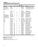
Main Motor Overload
(continued)
I/O Mod Com Error,
Com Mod Com Error,
Motor Mod Com Error
Oil Filter Maint., dP2 Oil
Filter High
P3 Oil Pressure Low,
P3 Oil Pressure Low,
dP3 Oil Pressure Low
P1 Sensor Fail, P2
Sensor Fail, P3 Sensor
Fail, P4 Sensor Fail, T1
Sensor Fail, T2 Sensor
Fail, T3 Sensor Fail, T4
Sensor Fail, T5 Sensor
Fail
dP1 Separator Maint.
P1-P2
Factory Setup Error
P1 Sump Pressure High
Module Network Error; The
Network that Connects the
Display Module, I/O Module and
Other Optional Modules is Not
Working Correctly
Pressure Across Oil Filter
Above 20 psi (1.4 bar) while
running
Oil Pressure Low
Sensor or Wiring Failure
Pressure Across Separator High
The Factory Setup Information
Needs to be Reviewed for
Correct Values
Sump Pressure High
Make sure unload pressure set
below limit of compressor
Check motor starter contacts for
proper operation.
Check line voltage, if low consult
power company.
Check wiring.
Replace module referred to in error
message, if problem persists
replace display module.
Oil filter clogged, replace oil filter.
Low ambient temperature, sump
heater may be required in ambients
below 40°F (4°C).
Sensor failure, check sensor, wiring
and tubing.
Oil pump failure, consult Sullair
service department.
Oil filter clogged, replace filter.
Sump oil level low, replenish oil to
proper level.
Low ambient temperature, sump
heater may be required in ambients
below 40°F (4°C).
Oil pump may be required for
remote coolers.
Check sensor wiring.
Check sensor.
Plugged separator elements,
replace.
Pressure sensor failure, check sen-
sor wiring.
If problem persists replace
Supervisor.
Sullicon, spiral or blowdown valve
failed, check valves.
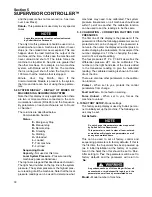
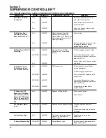
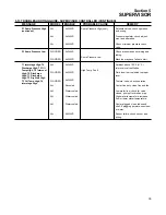
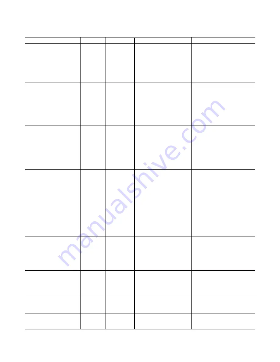
5.13 TROUBLESHOOTING GUIDE-
SUPERVISOR CONTROLLER (CONTINUED)
MESSAGE
MODEL
ENABLE
PROBABLE CAUSE
REMEDY
Summary of Contents for LS-32
Page 6: ...NOTES...
Page 14: ...Section 2 DESCRIPTION 8 Figure 2 2 Compressor Piping and Instrument Diagram 02250140 998R02...
Page 16: ...Section 2 DESCRIPTION 10 Figure 2 2 Compressor Piping and Instrument Diagram 02250140 998R02...
Page 21: ...Section 2 DESCRIPTION 15 Figure 2 5A Control System KEY COMPONENTS...
Page 22: ...Section 2 DESCRIPTION 16 Figure 2 5B Control System START...
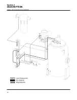
Page 23: ...Section 2 DESCRIPTION 17 Figure 2 5C Control System MODULATION...
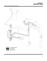
Page 24: ...Section 2 DESCRIPTION 18 Figure 2 5D Control System UNLOAD...
Page 25: ...Section 2 DESCRIPTION 19 Figure 2 5E Control System FULL LOAD...
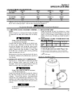
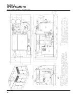
Page 28: ...Section 3 SPECIFICATIONS 22 Figure 3 2 Identification LS 32 Air cooled 02250140 997R01...
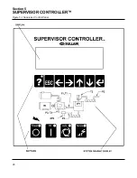
Page 32: ...Section 5 SUPERVISOR CONTROLLER 26 Figure 5 1 Supervisor Control Panel...
Page 44: ...38 NOTES...
Page 56: ...50 NOTES...
Page 59: ...53 NOTES...
Page 60: ...Section 8 ILLUSTRATIONS AND PARTS LIST 54 8 3 MOTOR COMPRESSOR FRAME AND PARTS 02250140 989R01...
Page 62: ...Section 8 ILLUSTRATIONS AND PARTS LIST 56 8 3 MOTOR COMPRESSOR FRAME AND PARTS 02250140 989R01...
Page 64: ...Section 8 ILLUSTRATIONS AND PARTS LIST 58 8 4 AIR INLET SYSTEM 02250140 990R02...
Page 66: ...Section 8 ILLUSTRATIONS AND PARTS LIST 60 8 4 AIR INLET SYSTEM 02250140 990R02...
Page 68: ...Section 8 ILLUSTRATIONS AND PARTS LIST 62 8 5 FLUID COOLING SYSTEM AIR COOLED 02250140 994R00...
Page 70: ...Section 8 ILLUSTRATIONS AND PARTS LIST 64 8 5 FLUID COOLING SYSTEM AIR COOLED 02250140 994R00...
Page 72: ...Section 8 ILLUSTRATIONS AND PARTS LIST 66 8 6 AIR PIPING SYSTEM AIR COOLED 02250140 992R01...
Page 74: ...Section 8 ILLUSTRATIONS AND PARTS LIST 68 8 6 AIR PIPING SYSTEM AIR COOLED 02250140 992R01...
Page 76: ...Section 8 ILLUSTRATIONS AND PARTS LIST 70 02250140 993R01 8 7 FLUID PIPING SYSTEM AIR COOLER...
Page 78: ...Section 8 ILLUSTRATIONS AND PARTS LIST 72 02250140 993R01 8 7 FLUID PIPING SYSTEM AIR COOLER...
Page 80: ...Section 8 ILLUSTRATIONS AND PARTS LIST 74 02250140 991R00 8 8 SUMP AND PARTS...
Page 82: ...Section 8 ILLUSTRATIONS AND PARTS LIST 76 02250140 991R00 8 8 SUMP AND PARTS...
Page 84: ...Section 8 ILLUSTRATIONS AND PARTS LIST 78 8 9 SULLICON CONTROL 02250134 158R00...
Page 86: ...Section 8 ILLUSTRATIONS AND PARTS LIST 80 8 10 COMPRESSOR ACTUATOR...
Page 88: ...Section 8 ILLUSTRATIONS AND PARTS LIST 82 8 11 PNEUMATIC CONTROLS 02250140 996R00...
Page 90: ...Section 8 ILLUSTRATIONS AND PARTS LIST 84 8 11 PNEUMATIC CONTROLS 02250140 996R00...
Page 92: ...Section 8 ILLUSTRATIONS AND PARTS LIST 86 8 11 PNEUMATIC CONTROLS 02250140 996R00...
Page 94: ...Section 8 ILLUSTRATIONS AND PARTS LIST 88 8 12 CONTROL BOX SOLID STATE 02250122 005R04...
Page 96: ...Section 8 ILLUSTRATIONS AND PARTS LIST 90 8 13 CONTROL BOX FULL VOLTAGE 02250122 511R04...
Page 98: ...Section 8 ILLUSTRATIONS AND PARTS LIST 92 8 14 CONTROL BOX WYE DELTA 02250122 516R08...
Page 100: ...Section 8 ILLUSTRATIONS AND PARTS LIST 94 8 15 ENCLOSURE AIR COOLED 02250140 995R00...
Page 102: ...Section 8 ILLUSTRATIONS AND PARTS LIST 96 8 15 ENCLOSURE AIR COOLED 02250140 995R00...
Page 104: ...Section 8 ILLUSTRATIONS AND PARTS LIST 98 8 16 DECAL GROUP...
Page 106: ...Section 8 ILLUSTRATIONS AND PARTS LIST 100 8 16 DECAL GROUP...
Page 108: ...Section 8 ILLUSTRATIONS AND PARTS LIST 102 8 16 DECAL GROUP...
Page 110: ...Section 8 ILLUSTRATIONS AND PARTS LIST 104 8 17 DECAL LOCATIONS...
Page 112: ...Section 8 ILLUSTRATIONS AND PARTS LIST 106 8 18 DECAL LOCATIONS ENCLOSURE...
Page 114: ...Section 8 ILLUSTRATIONS AND PARTS LIST 108 8 19 DECAL LOCATIONS CONTROL BOX...
Page 117: ...111 NOTES...

