Section 5
SUPERVISOR
29
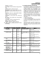
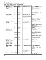
machine runs load/ no load. If modulate is set to
“No”, unload pressure must be reset to the rated
load pressure of the machine. For example, for an
L model rated for 100 psig full load operation, the
unload pressure must be set at 100 psig. This
ensures that the motor will not overload.
Language select -
English, German, Spanish,
Italian and French may be selected for display lan-
guage.
Temp Units -
Temperature units may be set to
degrees F or degrees C.
Press Units -
Pressure units may be set to psi, bar,
or kPa.
5.6 MAINTENANCE - PREVENTIVE MAINTENANCE
INFORMATION AND TIMERS
The following lines are on the Maintenance display.
Information -
The top two lines may be changed to
advise what to do when there is a maintenance
warning. For example a distributor can put in his
name and telephone number.
Ser. No -
Serial number of machine
Warn at -
When any one of the following drop
below this number, a warning is issued.
Oil Filter hours -
Hours before oil filter change
PN -
Oil Filter part number
Separator hours -
Hours before separator
change
Prim. -
Primary separator part number
Air Filter hours -
Hours before air filter change
Prim. -
Primary air filter part number
Sec. -
Secondary air filter part number
Oil hours -
Hours before oil change
PN -
Oil part number
Oil Anal. -
Hours before oil analysis
These hours and part numbers can be changed
using the enter and arrow keys.
Fault Log -
Log of previous faults.
The fault log shows the last 16 faults that occurred.
The top line of the display shows the run hours
where the fault occurred, and the second line
shows the fault. The faults can be scrolled through
using the up and down arrow keys. They are
ordered by most recent first. (ie. when the function
is entered the most recent fault is displayed.
Pressing the down arrow displays the next fault
etc).
Sensor Log -
Log of sensor readings leading up to
a fault.
The sensor log shows the sensor readings leading
up to a fault. The top line shows the last fault. The
following lines show T1, T2, P1 & P2. Each line rep-
resents readings that are 5 seconds apart for one
minute, then one minute apart for 10 minutes.
There is a second set of readings for T3, T4, P3 &
P4.
5.7 SEQUENCING - SEQUENCING & COMMUNICA-
TION PARAMETERS
Sequencing requires an optional communications
module.
The following parameters can be viewed and edit-
ed. For more details on sequencing see the
Supervisor Sequencing and Protocol Manual.
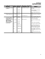
Sequence By - Sequencing mode can be set to:
Disabled - Control does not do any sequencing.
Remote - Enables Remote Start/Stop, Remote
Load/Unload and Local/Master inputs
Hours - Uses the Seq Hrs parameter to determine
order of sequencing
Number - Uses the Com Number to determine
order of sequencing
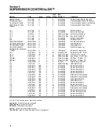
Seq Hrs -
This is an hour counter used when the
‘Sequence By’ parameter is set to ‘Hours’. Each
hour that the machine is running increments this
counter. When then ‘Sequence By’ parameter is set
to ‘Hours’, the machine with the least amount of
Seq Hrs is started first, and the machine with the
most Seq Hrs is shut off first.
Com Number -
Communications number. When
two or more machines are connected together
using the network (RS-485 channel), each machine
must have a unique number or address. These
must be assigned in numerical order. For example
in a three machine system the machine communi-
cations numbers should be 1,2 & 3.
Machines -
This is the total number of machines
connected to the network (RS-485 channel). For
example in a three machine system, this parameter
should be set to 3.
Low Press -
This is the lowest pressure allowed
before immediately starting a machine.
Recovery Time -
This parameter keeps multiple
machines from loading, unloading and starting at
the same time. For example if a low pressure con-
dition causes a machine to start, the next machine
will not start unless the Recovery Time has elapsed,
Summary of Contents for LS-32
Page 6: ...NOTES...
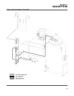
Page 14: ...Section 2 DESCRIPTION 8 Figure 2 2 Compressor Piping and Instrument Diagram 02250140 998R02...
Page 16: ...Section 2 DESCRIPTION 10 Figure 2 2 Compressor Piping and Instrument Diagram 02250140 998R02...
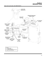
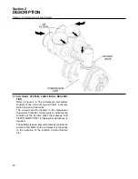
Page 21: ...Section 2 DESCRIPTION 15 Figure 2 5A Control System KEY COMPONENTS...
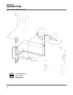
Page 22: ...Section 2 DESCRIPTION 16 Figure 2 5B Control System START...
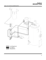
Page 23: ...Section 2 DESCRIPTION 17 Figure 2 5C Control System MODULATION...
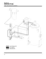
Page 24: ...Section 2 DESCRIPTION 18 Figure 2 5D Control System UNLOAD...
Page 25: ...Section 2 DESCRIPTION 19 Figure 2 5E Control System FULL LOAD...
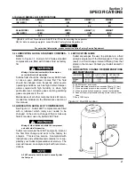
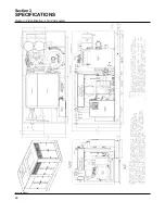
Page 28: ...Section 3 SPECIFICATIONS 22 Figure 3 2 Identification LS 32 Air cooled 02250140 997R01...
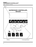
Page 32: ...Section 5 SUPERVISOR CONTROLLER 26 Figure 5 1 Supervisor Control Panel...
Page 44: ...38 NOTES...
Page 56: ...50 NOTES...
Page 59: ...53 NOTES...
Page 60: ...Section 8 ILLUSTRATIONS AND PARTS LIST 54 8 3 MOTOR COMPRESSOR FRAME AND PARTS 02250140 989R01...
Page 62: ...Section 8 ILLUSTRATIONS AND PARTS LIST 56 8 3 MOTOR COMPRESSOR FRAME AND PARTS 02250140 989R01...
Page 64: ...Section 8 ILLUSTRATIONS AND PARTS LIST 58 8 4 AIR INLET SYSTEM 02250140 990R02...
Page 66: ...Section 8 ILLUSTRATIONS AND PARTS LIST 60 8 4 AIR INLET SYSTEM 02250140 990R02...
Page 68: ...Section 8 ILLUSTRATIONS AND PARTS LIST 62 8 5 FLUID COOLING SYSTEM AIR COOLED 02250140 994R00...
Page 70: ...Section 8 ILLUSTRATIONS AND PARTS LIST 64 8 5 FLUID COOLING SYSTEM AIR COOLED 02250140 994R00...
Page 72: ...Section 8 ILLUSTRATIONS AND PARTS LIST 66 8 6 AIR PIPING SYSTEM AIR COOLED 02250140 992R01...
Page 74: ...Section 8 ILLUSTRATIONS AND PARTS LIST 68 8 6 AIR PIPING SYSTEM AIR COOLED 02250140 992R01...
Page 76: ...Section 8 ILLUSTRATIONS AND PARTS LIST 70 02250140 993R01 8 7 FLUID PIPING SYSTEM AIR COOLER...
Page 78: ...Section 8 ILLUSTRATIONS AND PARTS LIST 72 02250140 993R01 8 7 FLUID PIPING SYSTEM AIR COOLER...
Page 80: ...Section 8 ILLUSTRATIONS AND PARTS LIST 74 02250140 991R00 8 8 SUMP AND PARTS...
Page 82: ...Section 8 ILLUSTRATIONS AND PARTS LIST 76 02250140 991R00 8 8 SUMP AND PARTS...
Page 84: ...Section 8 ILLUSTRATIONS AND PARTS LIST 78 8 9 SULLICON CONTROL 02250134 158R00...
Page 86: ...Section 8 ILLUSTRATIONS AND PARTS LIST 80 8 10 COMPRESSOR ACTUATOR...
Page 88: ...Section 8 ILLUSTRATIONS AND PARTS LIST 82 8 11 PNEUMATIC CONTROLS 02250140 996R00...
Page 90: ...Section 8 ILLUSTRATIONS AND PARTS LIST 84 8 11 PNEUMATIC CONTROLS 02250140 996R00...
Page 92: ...Section 8 ILLUSTRATIONS AND PARTS LIST 86 8 11 PNEUMATIC CONTROLS 02250140 996R00...
Page 94: ...Section 8 ILLUSTRATIONS AND PARTS LIST 88 8 12 CONTROL BOX SOLID STATE 02250122 005R04...
Page 96: ...Section 8 ILLUSTRATIONS AND PARTS LIST 90 8 13 CONTROL BOX FULL VOLTAGE 02250122 511R04...
Page 98: ...Section 8 ILLUSTRATIONS AND PARTS LIST 92 8 14 CONTROL BOX WYE DELTA 02250122 516R08...
Page 100: ...Section 8 ILLUSTRATIONS AND PARTS LIST 94 8 15 ENCLOSURE AIR COOLED 02250140 995R00...
Page 102: ...Section 8 ILLUSTRATIONS AND PARTS LIST 96 8 15 ENCLOSURE AIR COOLED 02250140 995R00...
Page 104: ...Section 8 ILLUSTRATIONS AND PARTS LIST 98 8 16 DECAL GROUP...
Page 106: ...Section 8 ILLUSTRATIONS AND PARTS LIST 100 8 16 DECAL GROUP...
Page 108: ...Section 8 ILLUSTRATIONS AND PARTS LIST 102 8 16 DECAL GROUP...
Page 110: ...Section 8 ILLUSTRATIONS AND PARTS LIST 104 8 17 DECAL LOCATIONS...
Page 112: ...Section 8 ILLUSTRATIONS AND PARTS LIST 106 8 18 DECAL LOCATIONS ENCLOSURE...
Page 114: ...Section 8 ILLUSTRATIONS AND PARTS LIST 108 8 19 DECAL LOCATIONS CONTROL BOX...
Page 117: ...111 NOTES...

