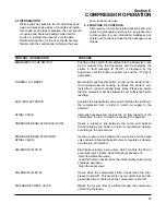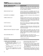
Section 3
SPECIFICATIONS
21
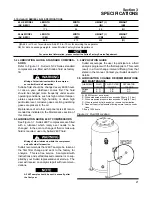
3.1 SULLAIR SERIES LS-32 SPECIFICATIONS
60 HZ MODEL
LENGTH
WIDTH
HEIGHT (I)
WEIGHT
(AC & WC)
(IN)
(IN)
(IN)
(LB)
175
84
88
(II)
50Hz MODEL
LENGTH
WIDTH
HEIGHT (I)
WEIGHT
(AC & WC)
(CM)
(CM)
(CM)
(KG)
445
213
224
(II)
(I)
Add 4 in./10 cm for enclosure. Add 27.5 in./70 cm for servicing the separator.
(II)
For data on package weights, consult Sullair Factory Sales Department.
For noise level information, please contact the Sullair Factory Service Department.
3.2 LUBRICATION GUIDE- STANDARD COMPRES-
SORS
. Sullair LS-32 Series standard
compressors are filled with Sullube fluid as factory
fill.
Mixing of other lubricants within the compres-
sor unit will void all warranties.
Sullube fluid should be changed every 8000 hours
or once a year, whichever comes first. The fluid
should be changed more frequently under severe
operating conditions, such as high ambient temper-
atures coupled with high humidity, or when high
particulate level, corrosive gases or strong oxidizing
gases are present in the air.
Maintenance of all other components is still recom-
mended as indicated in the Maintenance section of
this manual.
3.3 LUBRICATION GUIDE- 24KT COMPRESSORS
. Sullair 24KT compressors are filled
with a lubricant which rarely ever needs to be
changed. In the event a change of fluid or make-up
fluid is required, use only Sullair 24KT fluid.
Mixing of other lubricants within the compressor
unit will void all warranties.
Sullair recommends that 24KT sample be taken at
the first filter change and sent to the factory for
analysis. This is a free service. A sample kit with
instructions and self addressed container is to sup-
plied by your Sullair representative at start-up. The
user will receive an analysis report with recommen-
dations.
A 24KT sample should be sent in annually, after
the first year.
3.4 APPLICATION GUIDE
Sullair encourages the user to participate in a fluid
analysis program with the fluid suppliers. This could
result in a fluid change interval differing from that
stated in the manual. Contact your Sullair dealer for
details.
3.5 LUBRICATION CHANGE RECOMMENDATIONS
AND MAINTENANCE
LUBRICANT
FLUID
FLUID FILTER
SEPARATOR
CHANGE
CHANGE
CHANGE
Sullube
A, D
F, B
A, C
24KT
E, D
F, B
A, C
A - 8,000 Hours or once a year
B - When measured pressure loss exceeds 20 psig (1.3 bar).
C - When measured pressure loss exceeds 10 psig (0.7 bar).
D - When required by fluid analysis or known contamination.
E - Does not require replacement during normal service condi-
tions.
F- Every 1000 hours.
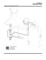
Figure 3-1 Fluid Fill Location
Summary of Contents for LS-32
Page 6: ...NOTES...
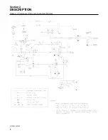
Page 14: ...Section 2 DESCRIPTION 8 Figure 2 2 Compressor Piping and Instrument Diagram 02250140 998R02...
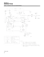
Page 16: ...Section 2 DESCRIPTION 10 Figure 2 2 Compressor Piping and Instrument Diagram 02250140 998R02...
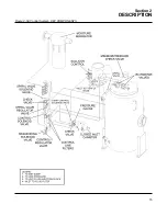
Page 21: ...Section 2 DESCRIPTION 15 Figure 2 5A Control System KEY COMPONENTS...
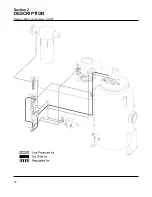
Page 22: ...Section 2 DESCRIPTION 16 Figure 2 5B Control System START...
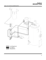
Page 23: ...Section 2 DESCRIPTION 17 Figure 2 5C Control System MODULATION...
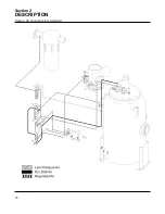
Page 24: ...Section 2 DESCRIPTION 18 Figure 2 5D Control System UNLOAD...
Page 25: ...Section 2 DESCRIPTION 19 Figure 2 5E Control System FULL LOAD...
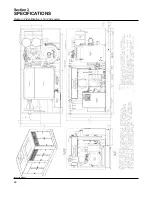
Page 28: ...Section 3 SPECIFICATIONS 22 Figure 3 2 Identification LS 32 Air cooled 02250140 997R01...
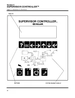
Page 32: ...Section 5 SUPERVISOR CONTROLLER 26 Figure 5 1 Supervisor Control Panel...
Page 44: ...38 NOTES...
Page 56: ...50 NOTES...
Page 59: ...53 NOTES...
Page 60: ...Section 8 ILLUSTRATIONS AND PARTS LIST 54 8 3 MOTOR COMPRESSOR FRAME AND PARTS 02250140 989R01...
Page 62: ...Section 8 ILLUSTRATIONS AND PARTS LIST 56 8 3 MOTOR COMPRESSOR FRAME AND PARTS 02250140 989R01...
Page 64: ...Section 8 ILLUSTRATIONS AND PARTS LIST 58 8 4 AIR INLET SYSTEM 02250140 990R02...
Page 66: ...Section 8 ILLUSTRATIONS AND PARTS LIST 60 8 4 AIR INLET SYSTEM 02250140 990R02...
Page 68: ...Section 8 ILLUSTRATIONS AND PARTS LIST 62 8 5 FLUID COOLING SYSTEM AIR COOLED 02250140 994R00...
Page 70: ...Section 8 ILLUSTRATIONS AND PARTS LIST 64 8 5 FLUID COOLING SYSTEM AIR COOLED 02250140 994R00...
Page 72: ...Section 8 ILLUSTRATIONS AND PARTS LIST 66 8 6 AIR PIPING SYSTEM AIR COOLED 02250140 992R01...
Page 74: ...Section 8 ILLUSTRATIONS AND PARTS LIST 68 8 6 AIR PIPING SYSTEM AIR COOLED 02250140 992R01...
Page 76: ...Section 8 ILLUSTRATIONS AND PARTS LIST 70 02250140 993R01 8 7 FLUID PIPING SYSTEM AIR COOLER...
Page 78: ...Section 8 ILLUSTRATIONS AND PARTS LIST 72 02250140 993R01 8 7 FLUID PIPING SYSTEM AIR COOLER...
Page 80: ...Section 8 ILLUSTRATIONS AND PARTS LIST 74 02250140 991R00 8 8 SUMP AND PARTS...
Page 82: ...Section 8 ILLUSTRATIONS AND PARTS LIST 76 02250140 991R00 8 8 SUMP AND PARTS...
Page 84: ...Section 8 ILLUSTRATIONS AND PARTS LIST 78 8 9 SULLICON CONTROL 02250134 158R00...
Page 86: ...Section 8 ILLUSTRATIONS AND PARTS LIST 80 8 10 COMPRESSOR ACTUATOR...
Page 88: ...Section 8 ILLUSTRATIONS AND PARTS LIST 82 8 11 PNEUMATIC CONTROLS 02250140 996R00...
Page 90: ...Section 8 ILLUSTRATIONS AND PARTS LIST 84 8 11 PNEUMATIC CONTROLS 02250140 996R00...
Page 92: ...Section 8 ILLUSTRATIONS AND PARTS LIST 86 8 11 PNEUMATIC CONTROLS 02250140 996R00...
Page 94: ...Section 8 ILLUSTRATIONS AND PARTS LIST 88 8 12 CONTROL BOX SOLID STATE 02250122 005R04...
Page 96: ...Section 8 ILLUSTRATIONS AND PARTS LIST 90 8 13 CONTROL BOX FULL VOLTAGE 02250122 511R04...
Page 98: ...Section 8 ILLUSTRATIONS AND PARTS LIST 92 8 14 CONTROL BOX WYE DELTA 02250122 516R08...
Page 100: ...Section 8 ILLUSTRATIONS AND PARTS LIST 94 8 15 ENCLOSURE AIR COOLED 02250140 995R00...
Page 102: ...Section 8 ILLUSTRATIONS AND PARTS LIST 96 8 15 ENCLOSURE AIR COOLED 02250140 995R00...
Page 104: ...Section 8 ILLUSTRATIONS AND PARTS LIST 98 8 16 DECAL GROUP...
Page 106: ...Section 8 ILLUSTRATIONS AND PARTS LIST 100 8 16 DECAL GROUP...
Page 108: ...Section 8 ILLUSTRATIONS AND PARTS LIST 102 8 16 DECAL GROUP...
Page 110: ...Section 8 ILLUSTRATIONS AND PARTS LIST 104 8 17 DECAL LOCATIONS...
Page 112: ...Section 8 ILLUSTRATIONS AND PARTS LIST 106 8 18 DECAL LOCATIONS ENCLOSURE...
Page 114: ...Section 8 ILLUSTRATIONS AND PARTS LIST 108 8 19 DECAL LOCATIONS CONTROL BOX...
Page 117: ...111 NOTES...

