Section 2
DESCRIPTION
12
before doing so.
Fluid is added to the sump via a capped fluid filler
opening, placed low on the receiver tank to prevent
over-filling of the sump. Two sight glasses enables
the operator to visually monitor the sump fluid level.
2.6 CONTROL SYSTEM, FUNCTIONAL DESCRIP-
TION
The purpose of the compressor control system is to
regulate the amount of air being compressed to
match the amount of compressed air being used.
The capacity control system consists of a spiral
valve and an inlet butterfly valve. The functional
description of the control system is described below
in 4 distinct phases of compressor operation. The
following applies to LS-32 Series compressors
ranging from 350 through 400HP. For explanatory
purposes, this description applies to any compres-
sor with an operating range of 60 to 70 psig (4.2 to
4.8 bar). A compressor with any other pressure
range would operate in the same manner except for
the stated pressures.
START MODE - 0 TO 40 PSIG (0 TO 2.8 BAR)
When the compressor
(ON) pad is depressed,
the sump pressure will quickly rise from 0 to 40 psig
(0 to 2.8 bar). During this period, both of the pres-
sure regulators and the solenoid valve are closed
and the Sullicon Control and spiral valve are inop-
erative. The spring on the control holds the butterfly
valve fully open while the spiral valve is fully closed
(maximum) position and the compressor pumps at
full rated capacity. The rising compressor air pres-
sure is isolated from the service line in this phase
by the minimum pressure valve set at approximate-
ly 40 psig (2.8 bar).
A standard closed inlet system is provided which
uses air pressure to close the butterfly and opens
the spiral valve to reduce motor torque for starting.
FULL LOAD MODE - 40 TO 60 PSIG (2.8 TO 4.2
BAR)
When the compressed air pressure in the sump
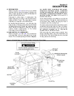
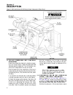
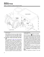
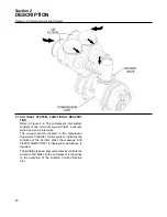
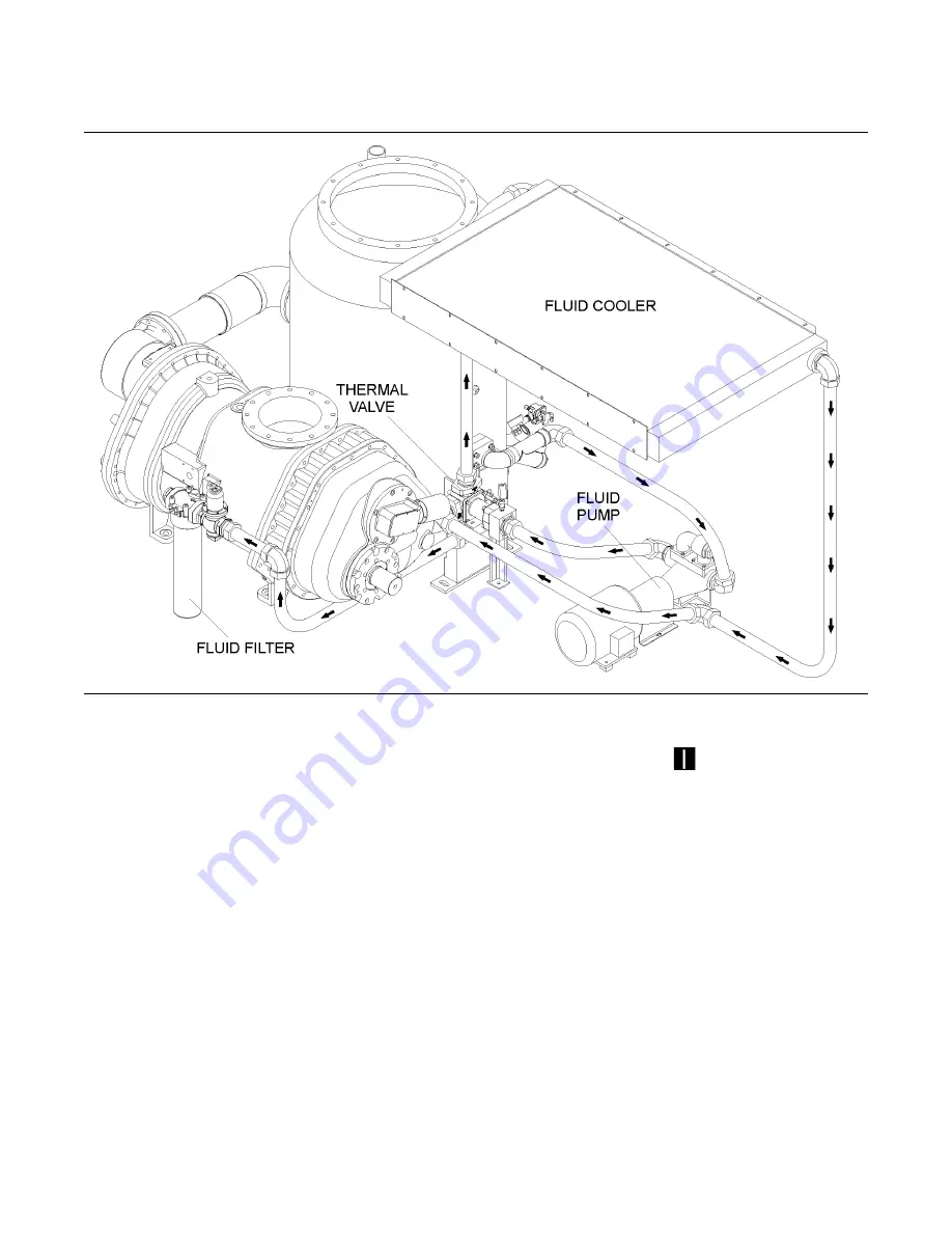
Figure 2-3 Compressor Cooling and Lubrication System
Summary of Contents for LS-32
Page 6: ...NOTES...
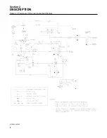
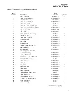
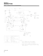
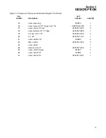
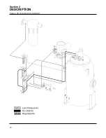
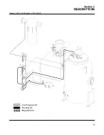
Page 14: ...Section 2 DESCRIPTION 8 Figure 2 2 Compressor Piping and Instrument Diagram 02250140 998R02...
Page 16: ...Section 2 DESCRIPTION 10 Figure 2 2 Compressor Piping and Instrument Diagram 02250140 998R02...
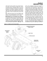
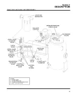
Page 21: ...Section 2 DESCRIPTION 15 Figure 2 5A Control System KEY COMPONENTS...
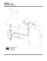
Page 22: ...Section 2 DESCRIPTION 16 Figure 2 5B Control System START...
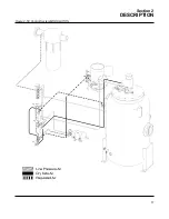
Page 23: ...Section 2 DESCRIPTION 17 Figure 2 5C Control System MODULATION...
Page 24: ...Section 2 DESCRIPTION 18 Figure 2 5D Control System UNLOAD...
Page 25: ...Section 2 DESCRIPTION 19 Figure 2 5E Control System FULL LOAD...
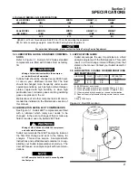
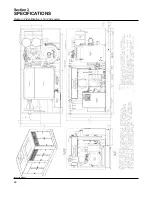
Page 28: ...Section 3 SPECIFICATIONS 22 Figure 3 2 Identification LS 32 Air cooled 02250140 997R01...
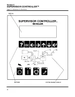
Page 32: ...Section 5 SUPERVISOR CONTROLLER 26 Figure 5 1 Supervisor Control Panel...
Page 44: ...38 NOTES...
Page 56: ...50 NOTES...
Page 59: ...53 NOTES...
Page 60: ...Section 8 ILLUSTRATIONS AND PARTS LIST 54 8 3 MOTOR COMPRESSOR FRAME AND PARTS 02250140 989R01...
Page 62: ...Section 8 ILLUSTRATIONS AND PARTS LIST 56 8 3 MOTOR COMPRESSOR FRAME AND PARTS 02250140 989R01...
Page 64: ...Section 8 ILLUSTRATIONS AND PARTS LIST 58 8 4 AIR INLET SYSTEM 02250140 990R02...
Page 66: ...Section 8 ILLUSTRATIONS AND PARTS LIST 60 8 4 AIR INLET SYSTEM 02250140 990R02...
Page 68: ...Section 8 ILLUSTRATIONS AND PARTS LIST 62 8 5 FLUID COOLING SYSTEM AIR COOLED 02250140 994R00...
Page 70: ...Section 8 ILLUSTRATIONS AND PARTS LIST 64 8 5 FLUID COOLING SYSTEM AIR COOLED 02250140 994R00...
Page 72: ...Section 8 ILLUSTRATIONS AND PARTS LIST 66 8 6 AIR PIPING SYSTEM AIR COOLED 02250140 992R01...
Page 74: ...Section 8 ILLUSTRATIONS AND PARTS LIST 68 8 6 AIR PIPING SYSTEM AIR COOLED 02250140 992R01...
Page 76: ...Section 8 ILLUSTRATIONS AND PARTS LIST 70 02250140 993R01 8 7 FLUID PIPING SYSTEM AIR COOLER...
Page 78: ...Section 8 ILLUSTRATIONS AND PARTS LIST 72 02250140 993R01 8 7 FLUID PIPING SYSTEM AIR COOLER...
Page 80: ...Section 8 ILLUSTRATIONS AND PARTS LIST 74 02250140 991R00 8 8 SUMP AND PARTS...
Page 82: ...Section 8 ILLUSTRATIONS AND PARTS LIST 76 02250140 991R00 8 8 SUMP AND PARTS...
Page 84: ...Section 8 ILLUSTRATIONS AND PARTS LIST 78 8 9 SULLICON CONTROL 02250134 158R00...
Page 86: ...Section 8 ILLUSTRATIONS AND PARTS LIST 80 8 10 COMPRESSOR ACTUATOR...
Page 88: ...Section 8 ILLUSTRATIONS AND PARTS LIST 82 8 11 PNEUMATIC CONTROLS 02250140 996R00...
Page 90: ...Section 8 ILLUSTRATIONS AND PARTS LIST 84 8 11 PNEUMATIC CONTROLS 02250140 996R00...
Page 92: ...Section 8 ILLUSTRATIONS AND PARTS LIST 86 8 11 PNEUMATIC CONTROLS 02250140 996R00...
Page 94: ...Section 8 ILLUSTRATIONS AND PARTS LIST 88 8 12 CONTROL BOX SOLID STATE 02250122 005R04...
Page 96: ...Section 8 ILLUSTRATIONS AND PARTS LIST 90 8 13 CONTROL BOX FULL VOLTAGE 02250122 511R04...
Page 98: ...Section 8 ILLUSTRATIONS AND PARTS LIST 92 8 14 CONTROL BOX WYE DELTA 02250122 516R08...
Page 100: ...Section 8 ILLUSTRATIONS AND PARTS LIST 94 8 15 ENCLOSURE AIR COOLED 02250140 995R00...
Page 102: ...Section 8 ILLUSTRATIONS AND PARTS LIST 96 8 15 ENCLOSURE AIR COOLED 02250140 995R00...
Page 104: ...Section 8 ILLUSTRATIONS AND PARTS LIST 98 8 16 DECAL GROUP...
Page 106: ...Section 8 ILLUSTRATIONS AND PARTS LIST 100 8 16 DECAL GROUP...
Page 108: ...Section 8 ILLUSTRATIONS AND PARTS LIST 102 8 16 DECAL GROUP...
Page 110: ...Section 8 ILLUSTRATIONS AND PARTS LIST 104 8 17 DECAL LOCATIONS...
Page 112: ...Section 8 ILLUSTRATIONS AND PARTS LIST 106 8 18 DECAL LOCATIONS ENCLOSURE...
Page 114: ...Section 8 ILLUSTRATIONS AND PARTS LIST 108 8 19 DECAL LOCATIONS CONTROL BOX...
Page 117: ...111 NOTES...

