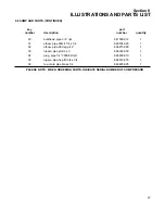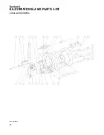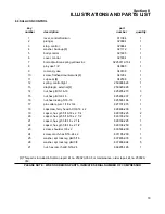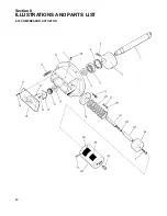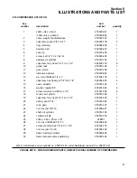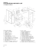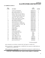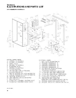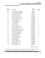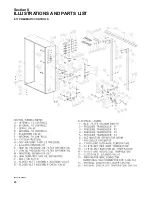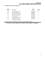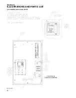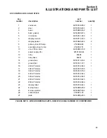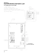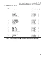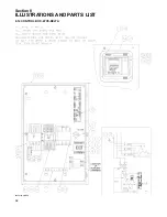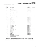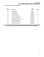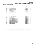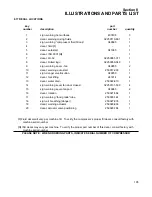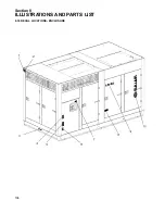
8.13 CONTROL BOX- FULL VOLTAGE
key
part
number
description
number
quantity
1 enclosure
02550108-859
1
2 door
02550109-465
1
3 bezel
02250129-958
1
4 bezel
gasket
02550090-872
1
5 I/O
module
02550141-089
1
6 transformer
24v
02250135-283
1
7
primary fuse 3.5 amp
250026-648
2
8
secondary fuse 5 amp
250019-751
1
9
univ. 250 va trans
02250083-188
1
10
univ. 350 va trans
02250083-190
-
11
primary fuse 4 amp
250026-649
-
12
secondary fuse 6 a
250019-762
-
13 ground
bus
02550110-334
1
14 ground
bar
02550101-721
1
15 display
module
02550119-330
1
16 display
label
02550130-344
1
17
starter9 size 5
250038-284
1
18
starter9 size 5dp
02250113-513
-
19
starter9 size 6
250038-285
-
20
display module gasket
02250048-822
2
21 E-stop
operator
02250085-504
1
22
contact block I-NC
250027-125
1
23 E-stop
decal
02250086-259
1
24 plate
02250086-265
1
PLEASE NOTE: WHEN ORDERING PARTS, INDICATE SERIAL NUMBER OF COMPRESSOR
Section 8
ILLUSTRATIONS AND PARTS LIST
91
Summary of Contents for LS-32
Page 6: ...NOTES...
Page 14: ...Section 2 DESCRIPTION 8 Figure 2 2 Compressor Piping and Instrument Diagram 02250140 998R02...
Page 16: ...Section 2 DESCRIPTION 10 Figure 2 2 Compressor Piping and Instrument Diagram 02250140 998R02...
Page 21: ...Section 2 DESCRIPTION 15 Figure 2 5A Control System KEY COMPONENTS...
Page 22: ...Section 2 DESCRIPTION 16 Figure 2 5B Control System START...
Page 23: ...Section 2 DESCRIPTION 17 Figure 2 5C Control System MODULATION...
Page 24: ...Section 2 DESCRIPTION 18 Figure 2 5D Control System UNLOAD...
Page 25: ...Section 2 DESCRIPTION 19 Figure 2 5E Control System FULL LOAD...
Page 28: ...Section 3 SPECIFICATIONS 22 Figure 3 2 Identification LS 32 Air cooled 02250140 997R01...
Page 32: ...Section 5 SUPERVISOR CONTROLLER 26 Figure 5 1 Supervisor Control Panel...
Page 44: ...38 NOTES...
Page 56: ...50 NOTES...
Page 59: ...53 NOTES...
Page 60: ...Section 8 ILLUSTRATIONS AND PARTS LIST 54 8 3 MOTOR COMPRESSOR FRAME AND PARTS 02250140 989R01...
Page 62: ...Section 8 ILLUSTRATIONS AND PARTS LIST 56 8 3 MOTOR COMPRESSOR FRAME AND PARTS 02250140 989R01...
Page 64: ...Section 8 ILLUSTRATIONS AND PARTS LIST 58 8 4 AIR INLET SYSTEM 02250140 990R02...
Page 66: ...Section 8 ILLUSTRATIONS AND PARTS LIST 60 8 4 AIR INLET SYSTEM 02250140 990R02...
Page 68: ...Section 8 ILLUSTRATIONS AND PARTS LIST 62 8 5 FLUID COOLING SYSTEM AIR COOLED 02250140 994R00...
Page 70: ...Section 8 ILLUSTRATIONS AND PARTS LIST 64 8 5 FLUID COOLING SYSTEM AIR COOLED 02250140 994R00...
Page 72: ...Section 8 ILLUSTRATIONS AND PARTS LIST 66 8 6 AIR PIPING SYSTEM AIR COOLED 02250140 992R01...
Page 74: ...Section 8 ILLUSTRATIONS AND PARTS LIST 68 8 6 AIR PIPING SYSTEM AIR COOLED 02250140 992R01...
Page 76: ...Section 8 ILLUSTRATIONS AND PARTS LIST 70 02250140 993R01 8 7 FLUID PIPING SYSTEM AIR COOLER...
Page 78: ...Section 8 ILLUSTRATIONS AND PARTS LIST 72 02250140 993R01 8 7 FLUID PIPING SYSTEM AIR COOLER...
Page 80: ...Section 8 ILLUSTRATIONS AND PARTS LIST 74 02250140 991R00 8 8 SUMP AND PARTS...
Page 82: ...Section 8 ILLUSTRATIONS AND PARTS LIST 76 02250140 991R00 8 8 SUMP AND PARTS...
Page 84: ...Section 8 ILLUSTRATIONS AND PARTS LIST 78 8 9 SULLICON CONTROL 02250134 158R00...
Page 86: ...Section 8 ILLUSTRATIONS AND PARTS LIST 80 8 10 COMPRESSOR ACTUATOR...
Page 88: ...Section 8 ILLUSTRATIONS AND PARTS LIST 82 8 11 PNEUMATIC CONTROLS 02250140 996R00...
Page 90: ...Section 8 ILLUSTRATIONS AND PARTS LIST 84 8 11 PNEUMATIC CONTROLS 02250140 996R00...
Page 92: ...Section 8 ILLUSTRATIONS AND PARTS LIST 86 8 11 PNEUMATIC CONTROLS 02250140 996R00...
Page 94: ...Section 8 ILLUSTRATIONS AND PARTS LIST 88 8 12 CONTROL BOX SOLID STATE 02250122 005R04...
Page 96: ...Section 8 ILLUSTRATIONS AND PARTS LIST 90 8 13 CONTROL BOX FULL VOLTAGE 02250122 511R04...
Page 98: ...Section 8 ILLUSTRATIONS AND PARTS LIST 92 8 14 CONTROL BOX WYE DELTA 02250122 516R08...
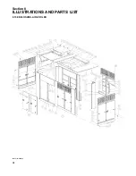
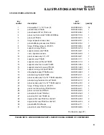
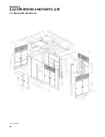
Page 100: ...Section 8 ILLUSTRATIONS AND PARTS LIST 94 8 15 ENCLOSURE AIR COOLED 02250140 995R00...
Page 102: ...Section 8 ILLUSTRATIONS AND PARTS LIST 96 8 15 ENCLOSURE AIR COOLED 02250140 995R00...
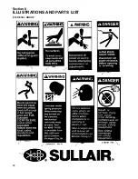
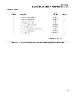
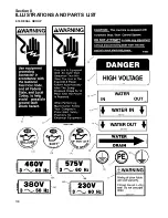
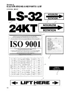
Page 104: ...Section 8 ILLUSTRATIONS AND PARTS LIST 98 8 16 DECAL GROUP...
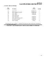
Page 106: ...Section 8 ILLUSTRATIONS AND PARTS LIST 100 8 16 DECAL GROUP...
Page 108: ...Section 8 ILLUSTRATIONS AND PARTS LIST 102 8 16 DECAL GROUP...
Page 110: ...Section 8 ILLUSTRATIONS AND PARTS LIST 104 8 17 DECAL LOCATIONS...
Page 112: ...Section 8 ILLUSTRATIONS AND PARTS LIST 106 8 18 DECAL LOCATIONS ENCLOSURE...
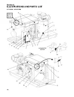
Page 114: ...Section 8 ILLUSTRATIONS AND PARTS LIST 108 8 19 DECAL LOCATIONS CONTROL BOX...
Page 117: ...111 NOTES...

