Section 4
INSTALLATION
23
4.1 MOUNTING OF COMPRESSOR
A foundation or mounting capable of supporting the
weight of the compressor, and rigid enough to main-
tain the compressor frame level and the compres-
sor in alignment is required. The compressor frame
must be leveled and secured with foundation bolts,
and full uniform contact must be maintained
between the frame and foundation. It is recom-
mended that the frame be grouted to the founda-
tion. The compressor unit and driver must be
aligned after installation as specified in the
Operator’s Manual. No piping loads shall be trans-
mitted to the compressor or the cooling package at
the external connections.
4.2 VENTILATION AND COOLING
For air-cooled compressors, select a location to
permit sufficient unobstructed air to flow in and out
of the compressor cooling package to keep the
operating temperature stable. The minimum dis-
tance that the compressor should be from sur-
rounding walls is four (4) feet (122 cm). To prevent
excessive ambient temperature rise, it is imperative
to provide adequate ventilation.
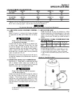
For water-cooled compressors, it is necessary to
check the cooling water supply. The water system
must be capable of supplying the following flows:
MODEL-HP/KW
WATER FLOW (GPM)
LS-32 400HP/299KW
87
Water flow requirements are based on 80°F to 85°F
(27°C to 29°C) water inlet temperature.
Recommended water pressure range is 40 to 75
psig (2.8 to 5.2 bar). Water flow rates will vary with
operating conditions. For rates based on criteria
other than that listed, consult your local Sullair
representative.
Table 4-1 Ventilation Requirements
below indicates
the ventilation requirements necessary to keep the
compressor running at a normal operating temper-
ature. The fan air requirement is the volume of air
which must flow through the compressor and/or
cooling package for proper ventilation. The speci-
fied heat rejection requirement is the amount of
heat that is radiated by the compressor. This heat
must be removed to assure a normal operating tem-
perature. With air-cooled compressors it is possible
to use this heat for space heating, providing exces-
sive pressure drop is not created across the fan.
Consult a Sullair office for assistance in utilizing this
heat.
DO NOT
install a water-cooled or an air-
cooled/aftercooled compressor without adequate
freeze protection where it will be exposed to tem-
perature less than 32°F(0°C).
4.3 SERVICE AIR PIPING
Service air piping should be installed as shown in
Figure
. A shut-off valve should be installed to
isolate a compressor from the service line if
required. Also notice that the service line should be
equipped with water legs and condensate drains
throughout the system.
4.4 COUPLING ALIGNMENT CHECK
In preparation for the factory test, the coupling sup-
plied with your compressor is properly aligned for
operation. After the compressor package has been
mounted to a foundation, it is necessary to recheck
the coupling alignment. Refer to Coupling
Alignment procedure explained in the Maintenance
section of this manual.
4.5 FLUID LEVEL CHECK
Your air compressor is also supplied with the prop-
er amount of fluid. However, it is necessary to
check the fluid level at installation. The level is
checked by looking at the sight glass located on the
sump. If the sump is properly filled, the coolant level
should fill 1/2 of the upper sight glass when the
compressor is shutdown. When the oil level falls
below the center of the lower sight glass, fluid must
be added.
4.6 ELECTRICAL PREPARATION
Interior electrical wiring is performed at the factory.
Required customer wiring is minimal, but should be
by a qualified electrician in compliance with OSHA,
National Electrical Code, and any other applicable
state or local electrical code concerning isolation
switches, fuse disconnects, etc. Sullair provides a
Table 4-1 Ventilation Requirements
WATER COOLED OR REMOTE COOLED
AIR-COOLED (I)
COMPRESSOR PACKAGE
COOLING PACKAGE
HEAT REJECTION
VENT FAN FLOW (II)
HEAT REJECTION
AIR FLOW
MODEL
MOTOR HP/KW
BTU/HR
CFM
BTU/HR
CFM
LS-32-400
400/299
91,000
8300
1,137,000
28,500
(I)
Applicable to air-cooled models only.
(II)
Applicable to compressors with enclosure.
Summary of Contents for LS-32
Page 6: ...NOTES...
Page 14: ...Section 2 DESCRIPTION 8 Figure 2 2 Compressor Piping and Instrument Diagram 02250140 998R02...
Page 16: ...Section 2 DESCRIPTION 10 Figure 2 2 Compressor Piping and Instrument Diagram 02250140 998R02...
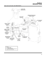
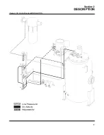
Page 21: ...Section 2 DESCRIPTION 15 Figure 2 5A Control System KEY COMPONENTS...
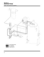
Page 22: ...Section 2 DESCRIPTION 16 Figure 2 5B Control System START...
Page 23: ...Section 2 DESCRIPTION 17 Figure 2 5C Control System MODULATION...
Page 24: ...Section 2 DESCRIPTION 18 Figure 2 5D Control System UNLOAD...
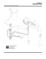
Page 25: ...Section 2 DESCRIPTION 19 Figure 2 5E Control System FULL LOAD...
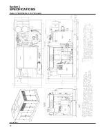
Page 28: ...Section 3 SPECIFICATIONS 22 Figure 3 2 Identification LS 32 Air cooled 02250140 997R01...
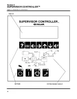
Page 32: ...Section 5 SUPERVISOR CONTROLLER 26 Figure 5 1 Supervisor Control Panel...
Page 44: ...38 NOTES...
Page 56: ...50 NOTES...
Page 59: ...53 NOTES...
Page 60: ...Section 8 ILLUSTRATIONS AND PARTS LIST 54 8 3 MOTOR COMPRESSOR FRAME AND PARTS 02250140 989R01...
Page 62: ...Section 8 ILLUSTRATIONS AND PARTS LIST 56 8 3 MOTOR COMPRESSOR FRAME AND PARTS 02250140 989R01...
Page 64: ...Section 8 ILLUSTRATIONS AND PARTS LIST 58 8 4 AIR INLET SYSTEM 02250140 990R02...
Page 66: ...Section 8 ILLUSTRATIONS AND PARTS LIST 60 8 4 AIR INLET SYSTEM 02250140 990R02...
Page 68: ...Section 8 ILLUSTRATIONS AND PARTS LIST 62 8 5 FLUID COOLING SYSTEM AIR COOLED 02250140 994R00...
Page 70: ...Section 8 ILLUSTRATIONS AND PARTS LIST 64 8 5 FLUID COOLING SYSTEM AIR COOLED 02250140 994R00...
Page 72: ...Section 8 ILLUSTRATIONS AND PARTS LIST 66 8 6 AIR PIPING SYSTEM AIR COOLED 02250140 992R01...
Page 74: ...Section 8 ILLUSTRATIONS AND PARTS LIST 68 8 6 AIR PIPING SYSTEM AIR COOLED 02250140 992R01...
Page 76: ...Section 8 ILLUSTRATIONS AND PARTS LIST 70 02250140 993R01 8 7 FLUID PIPING SYSTEM AIR COOLER...
Page 78: ...Section 8 ILLUSTRATIONS AND PARTS LIST 72 02250140 993R01 8 7 FLUID PIPING SYSTEM AIR COOLER...
Page 80: ...Section 8 ILLUSTRATIONS AND PARTS LIST 74 02250140 991R00 8 8 SUMP AND PARTS...
Page 82: ...Section 8 ILLUSTRATIONS AND PARTS LIST 76 02250140 991R00 8 8 SUMP AND PARTS...
Page 84: ...Section 8 ILLUSTRATIONS AND PARTS LIST 78 8 9 SULLICON CONTROL 02250134 158R00...
Page 86: ...Section 8 ILLUSTRATIONS AND PARTS LIST 80 8 10 COMPRESSOR ACTUATOR...
Page 88: ...Section 8 ILLUSTRATIONS AND PARTS LIST 82 8 11 PNEUMATIC CONTROLS 02250140 996R00...
Page 90: ...Section 8 ILLUSTRATIONS AND PARTS LIST 84 8 11 PNEUMATIC CONTROLS 02250140 996R00...
Page 92: ...Section 8 ILLUSTRATIONS AND PARTS LIST 86 8 11 PNEUMATIC CONTROLS 02250140 996R00...
Page 94: ...Section 8 ILLUSTRATIONS AND PARTS LIST 88 8 12 CONTROL BOX SOLID STATE 02250122 005R04...
Page 96: ...Section 8 ILLUSTRATIONS AND PARTS LIST 90 8 13 CONTROL BOX FULL VOLTAGE 02250122 511R04...
Page 98: ...Section 8 ILLUSTRATIONS AND PARTS LIST 92 8 14 CONTROL BOX WYE DELTA 02250122 516R08...
Page 100: ...Section 8 ILLUSTRATIONS AND PARTS LIST 94 8 15 ENCLOSURE AIR COOLED 02250140 995R00...
Page 102: ...Section 8 ILLUSTRATIONS AND PARTS LIST 96 8 15 ENCLOSURE AIR COOLED 02250140 995R00...
Page 104: ...Section 8 ILLUSTRATIONS AND PARTS LIST 98 8 16 DECAL GROUP...
Page 106: ...Section 8 ILLUSTRATIONS AND PARTS LIST 100 8 16 DECAL GROUP...
Page 108: ...Section 8 ILLUSTRATIONS AND PARTS LIST 102 8 16 DECAL GROUP...
Page 110: ...Section 8 ILLUSTRATIONS AND PARTS LIST 104 8 17 DECAL LOCATIONS...
Page 112: ...Section 8 ILLUSTRATIONS AND PARTS LIST 106 8 18 DECAL LOCATIONS ENCLOSURE...
Page 114: ...Section 8 ILLUSTRATIONS AND PARTS LIST 108 8 19 DECAL LOCATIONS CONTROL BOX...
Page 117: ...111 NOTES...

