Section 5
SUPERVISOR
31
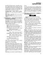
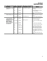
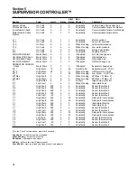
Cooling -
Air or Water
Press Trans -
Pressure transducer range 200, 250,
500
P1 Max -
Maximum discharge pressure
Water Switch -
Water pressure switch, Yes or No
Oil Switch -
Oil pressure differential switch, Yes or
No
Stop Timer -
Time to run machine before stopping.
Protect -
Protect control parameters
Load Hours -
Hours machine was running and
loaded
Run Hours -
Hours machine was running loaded
and unloaded
Load Cycles -
Number of load/unload cycles
Starts -
Number of machine starts
Capacity -
Maximum capacity of machine
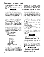
5.11 TEST- Used by Sullair personnel for trou-
bleshooting.
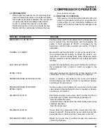
5.12 TROUBLESHOOTING INTRODUCTION
The information contained in the Troubleshooting
chart has been compiled from factory experience. It
contains symptoms and usual causes for the
described problems. However,
DO NOT
assume
that these are the only problems that may occur. All
available data concerning the trouble should be
systematically analyzed before undertaking any
repairs or component replacement procedures.
A detailed visual inspection is worth performing for
almost all problems and may avoid unnecessary
additional damage to the compressor. Always
remember to:
a. Check for loose wiring.
b. Check for damaged piping.
c. Check for parts damaged by heat or an electrical
short circuit, usually apparent by discoloration or a
burnt odor.
Should your problem persist after making the rec-
ommended check, consult your nearest Sullair
Distributor or the Sullair Corporation factory Service
Department.
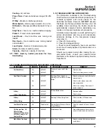
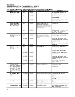
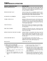
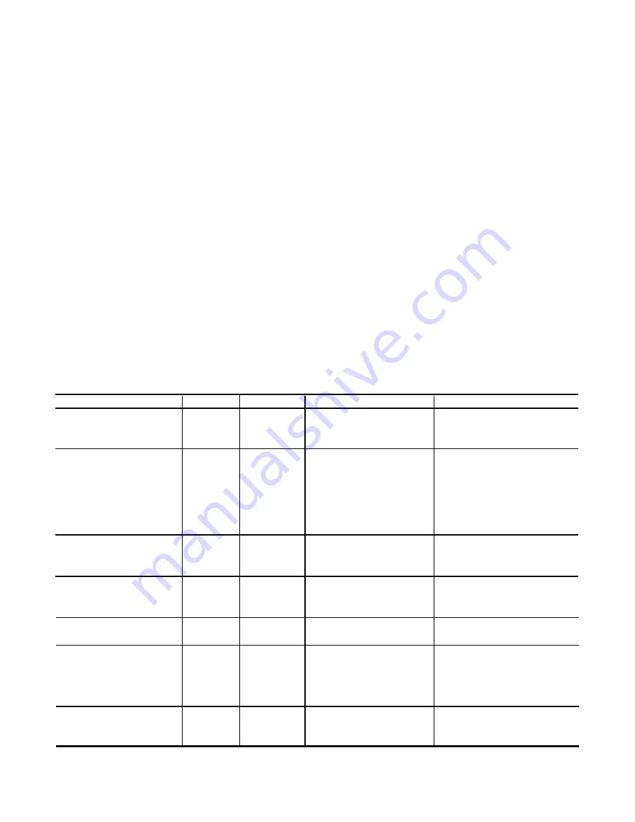
5.13 TROUBLESHOOTING GUIDE-
SUPERVISOR CONTROLLER
MESSAGE
MODEL
ENABLE
PROBABLE CAUSE
REMEDY
ALL
ALL
ALL
ALL
ALL
ALL
ALL
ALL
ALL
ALL
ALL
ALL
ALWAYS
ALWAYS
ALWAYS
ALWAYS
ALWAYS
ALWAYS
ALWAYS
ALWAYS
ALWAYS
Watercooled
ALWAYS
ALWAYS
Air Filter Maint
Aux Motor Overload
E-Stop
E-Stop Push Button
E-Stop
E-Stop String
Low Water Pressure
Oil Change Due, Oil
Filter Change,
Separator Change Due,
Air Filter Change, Oil
Analysis Due
Main Motor Overload
Replace filter.
Check inlet filter pressure switch.
Reset auxiliary overload after heater
element cools.
Check motor starter contact for
proper operation.
Check line voltage, if low consult
power company.
Release button.
Check wiring.
Check auxiliary E-Stop devices.
Check wiring.
Check for closed valves or broken
pipes.
Select Maintenance from menu to
see service due and part numbers.
Reset overload after heater element
cools down.
Pressure Across Inlet Filter
High
Auxiliary Motor Tripped on
Cooling Fan, Oil Pump or Other
Motor
E-Stop Button Active
Auxiliary E-Stop String Open
Cooling Water Pressure Below
10 psi (0.7bar)
Maintenance Due
Main Motor Overload
Summary of Contents for LS-32
Page 6: ...NOTES...
Page 14: ...Section 2 DESCRIPTION 8 Figure 2 2 Compressor Piping and Instrument Diagram 02250140 998R02...
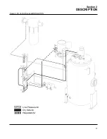
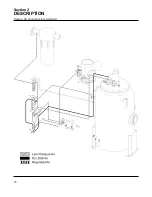
Page 16: ...Section 2 DESCRIPTION 10 Figure 2 2 Compressor Piping and Instrument Diagram 02250140 998R02...
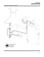
Page 21: ...Section 2 DESCRIPTION 15 Figure 2 5A Control System KEY COMPONENTS...
Page 22: ...Section 2 DESCRIPTION 16 Figure 2 5B Control System START...
Page 23: ...Section 2 DESCRIPTION 17 Figure 2 5C Control System MODULATION...
Page 24: ...Section 2 DESCRIPTION 18 Figure 2 5D Control System UNLOAD...
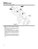
Page 25: ...Section 2 DESCRIPTION 19 Figure 2 5E Control System FULL LOAD...
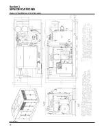
Page 28: ...Section 3 SPECIFICATIONS 22 Figure 3 2 Identification LS 32 Air cooled 02250140 997R01...
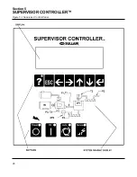
Page 32: ...Section 5 SUPERVISOR CONTROLLER 26 Figure 5 1 Supervisor Control Panel...
Page 44: ...38 NOTES...
Page 56: ...50 NOTES...
Page 59: ...53 NOTES...
Page 60: ...Section 8 ILLUSTRATIONS AND PARTS LIST 54 8 3 MOTOR COMPRESSOR FRAME AND PARTS 02250140 989R01...
Page 62: ...Section 8 ILLUSTRATIONS AND PARTS LIST 56 8 3 MOTOR COMPRESSOR FRAME AND PARTS 02250140 989R01...
Page 64: ...Section 8 ILLUSTRATIONS AND PARTS LIST 58 8 4 AIR INLET SYSTEM 02250140 990R02...
Page 66: ...Section 8 ILLUSTRATIONS AND PARTS LIST 60 8 4 AIR INLET SYSTEM 02250140 990R02...
Page 68: ...Section 8 ILLUSTRATIONS AND PARTS LIST 62 8 5 FLUID COOLING SYSTEM AIR COOLED 02250140 994R00...
Page 70: ...Section 8 ILLUSTRATIONS AND PARTS LIST 64 8 5 FLUID COOLING SYSTEM AIR COOLED 02250140 994R00...
Page 72: ...Section 8 ILLUSTRATIONS AND PARTS LIST 66 8 6 AIR PIPING SYSTEM AIR COOLED 02250140 992R01...
Page 74: ...Section 8 ILLUSTRATIONS AND PARTS LIST 68 8 6 AIR PIPING SYSTEM AIR COOLED 02250140 992R01...
Page 76: ...Section 8 ILLUSTRATIONS AND PARTS LIST 70 02250140 993R01 8 7 FLUID PIPING SYSTEM AIR COOLER...
Page 78: ...Section 8 ILLUSTRATIONS AND PARTS LIST 72 02250140 993R01 8 7 FLUID PIPING SYSTEM AIR COOLER...
Page 80: ...Section 8 ILLUSTRATIONS AND PARTS LIST 74 02250140 991R00 8 8 SUMP AND PARTS...
Page 82: ...Section 8 ILLUSTRATIONS AND PARTS LIST 76 02250140 991R00 8 8 SUMP AND PARTS...
Page 84: ...Section 8 ILLUSTRATIONS AND PARTS LIST 78 8 9 SULLICON CONTROL 02250134 158R00...
Page 86: ...Section 8 ILLUSTRATIONS AND PARTS LIST 80 8 10 COMPRESSOR ACTUATOR...
Page 88: ...Section 8 ILLUSTRATIONS AND PARTS LIST 82 8 11 PNEUMATIC CONTROLS 02250140 996R00...
Page 90: ...Section 8 ILLUSTRATIONS AND PARTS LIST 84 8 11 PNEUMATIC CONTROLS 02250140 996R00...
Page 92: ...Section 8 ILLUSTRATIONS AND PARTS LIST 86 8 11 PNEUMATIC CONTROLS 02250140 996R00...
Page 94: ...Section 8 ILLUSTRATIONS AND PARTS LIST 88 8 12 CONTROL BOX SOLID STATE 02250122 005R04...
Page 96: ...Section 8 ILLUSTRATIONS AND PARTS LIST 90 8 13 CONTROL BOX FULL VOLTAGE 02250122 511R04...
Page 98: ...Section 8 ILLUSTRATIONS AND PARTS LIST 92 8 14 CONTROL BOX WYE DELTA 02250122 516R08...
Page 100: ...Section 8 ILLUSTRATIONS AND PARTS LIST 94 8 15 ENCLOSURE AIR COOLED 02250140 995R00...
Page 102: ...Section 8 ILLUSTRATIONS AND PARTS LIST 96 8 15 ENCLOSURE AIR COOLED 02250140 995R00...
Page 104: ...Section 8 ILLUSTRATIONS AND PARTS LIST 98 8 16 DECAL GROUP...
Page 106: ...Section 8 ILLUSTRATIONS AND PARTS LIST 100 8 16 DECAL GROUP...
Page 108: ...Section 8 ILLUSTRATIONS AND PARTS LIST 102 8 16 DECAL GROUP...
Page 110: ...Section 8 ILLUSTRATIONS AND PARTS LIST 104 8 17 DECAL LOCATIONS...
Page 112: ...Section 8 ILLUSTRATIONS AND PARTS LIST 106 8 18 DECAL LOCATIONS ENCLOSURE...
Page 114: ...Section 8 ILLUSTRATIONS AND PARTS LIST 108 8 19 DECAL LOCATIONS CONTROL BOX...
Page 117: ...111 NOTES...

