Section 7
MAINTENANCE
39
7.1 GENERAL
As you proceed in reading this section, it will be
easy to see that the Maintenance Program for the
air compressor is quite minimal yet important. The
use of the service indicators provided for the fluid fil-
ter, air filter and fluid separator, will alert you when
service maintenance is required. When the mainte-
nance message is displayed by the Supervisor
Controller
TM
, maintenance for that specific item is
required. See instructions for each item in Section
7.7, Parts Replacement and Adjustment proce-
dures.
7.2 DAILY OPERATION
Prior to starting the compressor, it is necessary to
check the fluid level in the sump. Should the level
be low, simply add the necessary amount. If the
addition of fluid becomes too frequent, a simple
problem has developed which is causing this
excessive loss. See the Troubleshooting Section
(7.8) under Excessive Fluid Consumption for a
probable cause and remedy.
After a routine start has been made, observe the
Supervisor control panel and be sure it monitors the
correct readings for that particular phase of opera-
tion. After the compressor has warmed up, it is rec-
ommended that a general check of the overall com-
pressor and Supervisor be made to assure that the
compressor is running properly.
DO NOT remove caps, plugs, and/or other com-
ponents when compressor is running or pres-
surized.
Stop compressor and relieve all internal pres-
sure before doing so.
7.3 MAINTENANCE AFTER INITIAL 50 HOURS OF
OPERATION
After the initial 50 hours of operation, a few mainte-
nance requirements are needed to rid the system of
any foreign materials if any. Perform the following
maintenance operations to prevent unnecessary
problems.
1. Clean the return line strainers.
2. Clean the return line orifices.
3. Change the fluid filter element.
4. Clean the control line filters.
7.4 MAINTENANCE AFTER 1000 HOURS
After 1000 hours of operation, it will be necessary to
perform the following:
1. Clean the return line strainers.
2. Lubricate the Sullicon Control linkage.
3. Replace the fluid filter element.
7.5 FLUID CHANGE
Standard models are filled with the long life lubri-
cant Sullube.
Sullube should be changed under the following con-
ditions, whichever occurs first:
1. Every 8000 hours.
2. Once a year.
3. As indicated by fluid analysis.
A fluid sample analysis at every 4000 hours is rec-
ommended. Return fluid to Sullair Corporation in
Michigan City for free analysis. To facilitate this, a
sample bottle is included with the compressor.
7.6 SEPARATOR MAINTENANCE
Replace the separator elements when a message is
displayed or after one (1) year, whichever comes
first. The separator elements must be replaced.
DO
NOT
clean the separator elements.
7.7 PARTS REPLACEMENT AND ADJUSTMENT
PROCEDURES
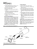
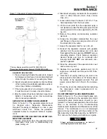
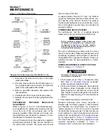
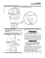
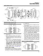
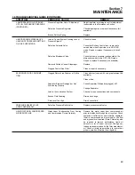
MAIN FILTER MAINTENANCE
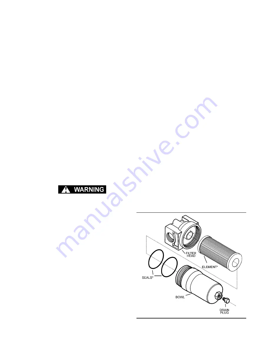
. The main filter (P/N 02250121-
638) is located schematically between the com-
pressor and the fluid stop valve. When servicing the
main filter, shut the compressor down, be sure all
pressure has been released, then follow the instruc-
tions below. For element replacement order kit
number 02250139-996.
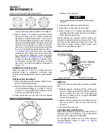
1. Drain the fluid from the canister by removing the
bottom drain plug
2. Loosen the spin-on canister using a wrench on
Figure 7-1 Main Filter (P/N 02250121-638)
*Repair Kit P/N 02250139-996
Summary of Contents for LS-32
Page 6: ...NOTES...
Page 14: ...Section 2 DESCRIPTION 8 Figure 2 2 Compressor Piping and Instrument Diagram 02250140 998R02...
Page 16: ...Section 2 DESCRIPTION 10 Figure 2 2 Compressor Piping and Instrument Diagram 02250140 998R02...
Page 21: ...Section 2 DESCRIPTION 15 Figure 2 5A Control System KEY COMPONENTS...
Page 22: ...Section 2 DESCRIPTION 16 Figure 2 5B Control System START...
Page 23: ...Section 2 DESCRIPTION 17 Figure 2 5C Control System MODULATION...
Page 24: ...Section 2 DESCRIPTION 18 Figure 2 5D Control System UNLOAD...
Page 25: ...Section 2 DESCRIPTION 19 Figure 2 5E Control System FULL LOAD...
Page 28: ...Section 3 SPECIFICATIONS 22 Figure 3 2 Identification LS 32 Air cooled 02250140 997R01...
Page 32: ...Section 5 SUPERVISOR CONTROLLER 26 Figure 5 1 Supervisor Control Panel...
Page 44: ...38 NOTES...
Page 56: ...50 NOTES...
Page 59: ...53 NOTES...
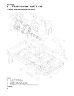
Page 60: ...Section 8 ILLUSTRATIONS AND PARTS LIST 54 8 3 MOTOR COMPRESSOR FRAME AND PARTS 02250140 989R01...
Page 62: ...Section 8 ILLUSTRATIONS AND PARTS LIST 56 8 3 MOTOR COMPRESSOR FRAME AND PARTS 02250140 989R01...
Page 64: ...Section 8 ILLUSTRATIONS AND PARTS LIST 58 8 4 AIR INLET SYSTEM 02250140 990R02...
Page 66: ...Section 8 ILLUSTRATIONS AND PARTS LIST 60 8 4 AIR INLET SYSTEM 02250140 990R02...
Page 68: ...Section 8 ILLUSTRATIONS AND PARTS LIST 62 8 5 FLUID COOLING SYSTEM AIR COOLED 02250140 994R00...
Page 70: ...Section 8 ILLUSTRATIONS AND PARTS LIST 64 8 5 FLUID COOLING SYSTEM AIR COOLED 02250140 994R00...
Page 72: ...Section 8 ILLUSTRATIONS AND PARTS LIST 66 8 6 AIR PIPING SYSTEM AIR COOLED 02250140 992R01...
Page 74: ...Section 8 ILLUSTRATIONS AND PARTS LIST 68 8 6 AIR PIPING SYSTEM AIR COOLED 02250140 992R01...
Page 76: ...Section 8 ILLUSTRATIONS AND PARTS LIST 70 02250140 993R01 8 7 FLUID PIPING SYSTEM AIR COOLER...
Page 78: ...Section 8 ILLUSTRATIONS AND PARTS LIST 72 02250140 993R01 8 7 FLUID PIPING SYSTEM AIR COOLER...
Page 80: ...Section 8 ILLUSTRATIONS AND PARTS LIST 74 02250140 991R00 8 8 SUMP AND PARTS...
Page 82: ...Section 8 ILLUSTRATIONS AND PARTS LIST 76 02250140 991R00 8 8 SUMP AND PARTS...
Page 84: ...Section 8 ILLUSTRATIONS AND PARTS LIST 78 8 9 SULLICON CONTROL 02250134 158R00...
Page 86: ...Section 8 ILLUSTRATIONS AND PARTS LIST 80 8 10 COMPRESSOR ACTUATOR...
Page 88: ...Section 8 ILLUSTRATIONS AND PARTS LIST 82 8 11 PNEUMATIC CONTROLS 02250140 996R00...
Page 90: ...Section 8 ILLUSTRATIONS AND PARTS LIST 84 8 11 PNEUMATIC CONTROLS 02250140 996R00...
Page 92: ...Section 8 ILLUSTRATIONS AND PARTS LIST 86 8 11 PNEUMATIC CONTROLS 02250140 996R00...
Page 94: ...Section 8 ILLUSTRATIONS AND PARTS LIST 88 8 12 CONTROL BOX SOLID STATE 02250122 005R04...
Page 96: ...Section 8 ILLUSTRATIONS AND PARTS LIST 90 8 13 CONTROL BOX FULL VOLTAGE 02250122 511R04...
Page 98: ...Section 8 ILLUSTRATIONS AND PARTS LIST 92 8 14 CONTROL BOX WYE DELTA 02250122 516R08...
Page 100: ...Section 8 ILLUSTRATIONS AND PARTS LIST 94 8 15 ENCLOSURE AIR COOLED 02250140 995R00...
Page 102: ...Section 8 ILLUSTRATIONS AND PARTS LIST 96 8 15 ENCLOSURE AIR COOLED 02250140 995R00...
Page 104: ...Section 8 ILLUSTRATIONS AND PARTS LIST 98 8 16 DECAL GROUP...
Page 106: ...Section 8 ILLUSTRATIONS AND PARTS LIST 100 8 16 DECAL GROUP...
Page 108: ...Section 8 ILLUSTRATIONS AND PARTS LIST 102 8 16 DECAL GROUP...
Page 110: ...Section 8 ILLUSTRATIONS AND PARTS LIST 104 8 17 DECAL LOCATIONS...
Page 112: ...Section 8 ILLUSTRATIONS AND PARTS LIST 106 8 18 DECAL LOCATIONS ENCLOSURE...
Page 114: ...Section 8 ILLUSTRATIONS AND PARTS LIST 108 8 19 DECAL LOCATIONS CONTROL BOX...
Page 117: ...111 NOTES...

