Section 5
SUPERVISOR CONTROLLER™
28
value. If during a change the ESC key is pushed,
editing is terminated and the original value is reset.
The left and right arrow keys can be used to move
to other digits or letters in a value. For example to
change a value from 100 to 500, the left arrow key
can be used to position the cursor to the 1 digit in
the 100, and the up arrow key used to increment
the digit to 5.
Text fields can also be edited in the same manner.
Push the enter key to start the edit, use the left and
right arrow keys to move to the letter to be changed,
then use the up and down arrow to change the let-
ter. Push the enter key to complete the edit.
The following are detailed descriptions of the vari-
ous displays.
5.4 STATUS - CURRENT PRESSURES, TEMPERA -
TURES, INPUTS AND OUTPUTS
All inputs and outputs are displayed showing both
the designator and the description (eg. T1-
Discharge) along with the selected temperature (C
or F) or pressure (psi, bar, kpa) units. Digital inputs
and outputs are shown either as a ‘0’ (zero) or ‘1’
(one). Zero is off and one is on. This is a view only
display.
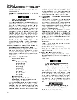
The order of display is :
Temperatures -
T1 through T5 depending on
model
Pressures -
P1 through P4 depending on model
Delta pressures -
dp1 through dp3 depending on
model
Load Hours -
Hours machine has run loaded
Run Hours -
Hours machine has run loaded or
unloaded
Load Cycles -
Number of load/unload cycles
Starts -
Number of time machine has started
E-Stop String
- E-Stop push button.
Aux E-Stop -
Auxiliary E-Stop, wired by customer.
Digital Inputs -
D1 through D10, depending on
model
Relay Outputs -
K1 through K8, depending on
model
5.5 CONTROL PARAMETERS - PRESSURE, TEM-
PERATURE AND TIMER SETTINGS
Parameters that control the operation of the
machine are viewed and set using this display.
These parameters may vary by machine model.
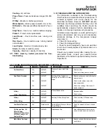
The Control Parameters are :
Unload pressure -
The pressure where the
machine is unloaded. For example if this parameter
is set to 110 psi (7.6 bar) the machine will unload
when the line pressure is above 110 psi (7.6 bar).
Load delta -
The pressure differential below the
unload pressure where the machine is loaded. For
example if the unload pressure is set to 110 psi
(7.6bar) and the load differential is set to 10 psid
(0.7 bar), the machine will load when the line pres-
sure goes below 100 psi (6.9 bar).
Unload Time -
If the machine is running in AUTO
mode, this parameter specifies the amount of time
that the machine will run unloaded before shutting
off. If the time is set less than 15 minutes (for exam-
ple 5), there may be times when the machine will
run unloaded for more than 5 minutes. This is
because there is another timer that keeps the
machine from being started more than four times an
hour.
Drain Interval -
If the machine has an optional elec-
tric solenoid drain, this parameter and the following
parameter (Drain Time) are used to turn on the
drain. The interval is the time between activations of
the drain and the Drain Time is the length of the
time energized. This does not apply to the Sullair
SCD zero loss drain, which is not controlled or mon-
itored by the Supervisor.
Drain Time -
Length of time that drain is energized.
Restart time -
Enabling this function also enables automatic
restart after power recovery. Be sure to depress
the Emergency Stop button to defeat this func-
tion when automatic start is to be prevented.
Time to wait after power up before starting machine.
This parameter is used to keep several machines
from starting at the same time after power up, or to
delay start until other equipment is started. If dis-
abled parameter is zero, the machine will not auto-
matically start after power up. If this parameter is a
number larger than zero, the machine restarts after
a delay defined by this time. For example, if the
Restart Time is set to 10 seconds, then the machine
will be enabled to start after 10 seconds.
Wye to delta transition timer -
Also used to con-
trol the closed inlet start valve. Disable by setting to
zero (0)-full voltage start (standard for full voltage
start). Requires approximately 4-6 seconds for wye-
delta or solid state starting.
Modulate -
If set to “No” the spiral valve and inlet
valve modulation control are disabled, and the
Summary of Contents for LS-32
Page 6: ...NOTES...
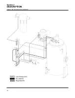
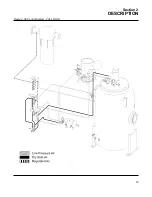
Page 14: ...Section 2 DESCRIPTION 8 Figure 2 2 Compressor Piping and Instrument Diagram 02250140 998R02...
Page 16: ...Section 2 DESCRIPTION 10 Figure 2 2 Compressor Piping and Instrument Diagram 02250140 998R02...
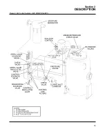
Page 21: ...Section 2 DESCRIPTION 15 Figure 2 5A Control System KEY COMPONENTS...
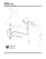
Page 22: ...Section 2 DESCRIPTION 16 Figure 2 5B Control System START...
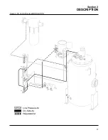
Page 23: ...Section 2 DESCRIPTION 17 Figure 2 5C Control System MODULATION...
Page 24: ...Section 2 DESCRIPTION 18 Figure 2 5D Control System UNLOAD...
Page 25: ...Section 2 DESCRIPTION 19 Figure 2 5E Control System FULL LOAD...
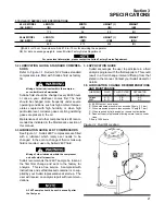
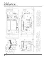
Page 28: ...Section 3 SPECIFICATIONS 22 Figure 3 2 Identification LS 32 Air cooled 02250140 997R01...
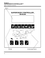
Page 32: ...Section 5 SUPERVISOR CONTROLLER 26 Figure 5 1 Supervisor Control Panel...
Page 44: ...38 NOTES...
Page 56: ...50 NOTES...
Page 59: ...53 NOTES...
Page 60: ...Section 8 ILLUSTRATIONS AND PARTS LIST 54 8 3 MOTOR COMPRESSOR FRAME AND PARTS 02250140 989R01...
Page 62: ...Section 8 ILLUSTRATIONS AND PARTS LIST 56 8 3 MOTOR COMPRESSOR FRAME AND PARTS 02250140 989R01...
Page 64: ...Section 8 ILLUSTRATIONS AND PARTS LIST 58 8 4 AIR INLET SYSTEM 02250140 990R02...
Page 66: ...Section 8 ILLUSTRATIONS AND PARTS LIST 60 8 4 AIR INLET SYSTEM 02250140 990R02...
Page 68: ...Section 8 ILLUSTRATIONS AND PARTS LIST 62 8 5 FLUID COOLING SYSTEM AIR COOLED 02250140 994R00...
Page 70: ...Section 8 ILLUSTRATIONS AND PARTS LIST 64 8 5 FLUID COOLING SYSTEM AIR COOLED 02250140 994R00...
Page 72: ...Section 8 ILLUSTRATIONS AND PARTS LIST 66 8 6 AIR PIPING SYSTEM AIR COOLED 02250140 992R01...
Page 74: ...Section 8 ILLUSTRATIONS AND PARTS LIST 68 8 6 AIR PIPING SYSTEM AIR COOLED 02250140 992R01...
Page 76: ...Section 8 ILLUSTRATIONS AND PARTS LIST 70 02250140 993R01 8 7 FLUID PIPING SYSTEM AIR COOLER...
Page 78: ...Section 8 ILLUSTRATIONS AND PARTS LIST 72 02250140 993R01 8 7 FLUID PIPING SYSTEM AIR COOLER...
Page 80: ...Section 8 ILLUSTRATIONS AND PARTS LIST 74 02250140 991R00 8 8 SUMP AND PARTS...
Page 82: ...Section 8 ILLUSTRATIONS AND PARTS LIST 76 02250140 991R00 8 8 SUMP AND PARTS...
Page 84: ...Section 8 ILLUSTRATIONS AND PARTS LIST 78 8 9 SULLICON CONTROL 02250134 158R00...
Page 86: ...Section 8 ILLUSTRATIONS AND PARTS LIST 80 8 10 COMPRESSOR ACTUATOR...
Page 88: ...Section 8 ILLUSTRATIONS AND PARTS LIST 82 8 11 PNEUMATIC CONTROLS 02250140 996R00...
Page 90: ...Section 8 ILLUSTRATIONS AND PARTS LIST 84 8 11 PNEUMATIC CONTROLS 02250140 996R00...
Page 92: ...Section 8 ILLUSTRATIONS AND PARTS LIST 86 8 11 PNEUMATIC CONTROLS 02250140 996R00...
Page 94: ...Section 8 ILLUSTRATIONS AND PARTS LIST 88 8 12 CONTROL BOX SOLID STATE 02250122 005R04...
Page 96: ...Section 8 ILLUSTRATIONS AND PARTS LIST 90 8 13 CONTROL BOX FULL VOLTAGE 02250122 511R04...
Page 98: ...Section 8 ILLUSTRATIONS AND PARTS LIST 92 8 14 CONTROL BOX WYE DELTA 02250122 516R08...
Page 100: ...Section 8 ILLUSTRATIONS AND PARTS LIST 94 8 15 ENCLOSURE AIR COOLED 02250140 995R00...
Page 102: ...Section 8 ILLUSTRATIONS AND PARTS LIST 96 8 15 ENCLOSURE AIR COOLED 02250140 995R00...
Page 104: ...Section 8 ILLUSTRATIONS AND PARTS LIST 98 8 16 DECAL GROUP...
Page 106: ...Section 8 ILLUSTRATIONS AND PARTS LIST 100 8 16 DECAL GROUP...
Page 108: ...Section 8 ILLUSTRATIONS AND PARTS LIST 102 8 16 DECAL GROUP...
Page 110: ...Section 8 ILLUSTRATIONS AND PARTS LIST 104 8 17 DECAL LOCATIONS...
Page 112: ...Section 8 ILLUSTRATIONS AND PARTS LIST 106 8 18 DECAL LOCATIONS ENCLOSURE...
Page 114: ...Section 8 ILLUSTRATIONS AND PARTS LIST 108 8 19 DECAL LOCATIONS CONTROL BOX...
Page 117: ...111 NOTES...

