Section 7
MAINTENANCE
45
adapter hubs.
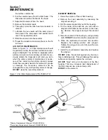
2. Place compressed assembly into position. If
additional compression is required, tighten each
installation/removal bolt on each end an addi-
tional 1/2 turn.
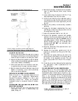
. Dip adapter bolt threads in
SAE 30 oil and insert bolts with lockwashers
through hub flange holes and engage tapped
holes in each adapter.
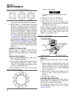
REMOVE ALL INSTAL-
LATION/REMOVAL BOLTS FROM BOTH
FLANGES
and put in a safe place for future use
should center section assembly require removal.
Tighten adapter bolts to the recommended
torque as given in
DISCPACK REPLACEMENT
Should discpacks require replacement, it is recom-
mended that new drive bolts, overload washers and
locknuts also be obtained. Order replacement kit
no. 02250044-346.
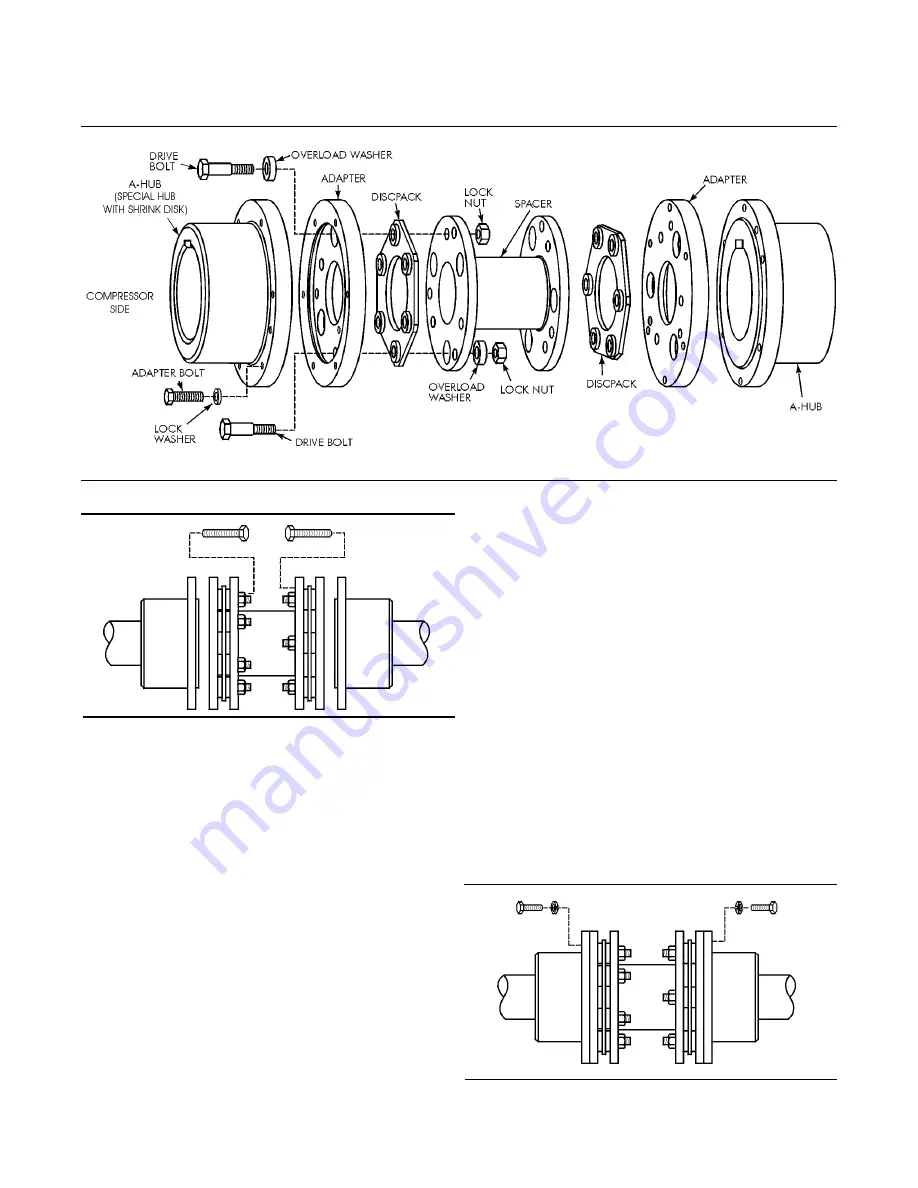
1. Remove old discpacks from adapters and spac-
er, and discard.
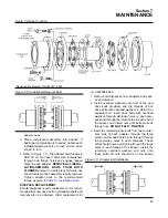
2. Install overload washers onto half of the new
drive bolts provided, and dip threads of ALL
drive bolts with overload washers in SAE 30 or
equivalent oil. Insert drive bolts with overload
washers through alternate holes in each disc-
pack and through the small holes in each end of
the spacer, and install nuts until bolts protrude
through nut.
DO NOT FULLY TIGHTEN
.
3. Insert the remaining drive bolts from the counter-
bore side of each adapter through the three
small non-threaded holes, and through through
the remaining holes in each discpack. These
bolts should now be protruding through the large
holes in each flange of the spacer. Install the
remaining overload washers and nuts onto
these bolts. All nuts should be on the spacer
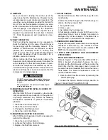
Figure 7-9 Drive Coupling
*Replacement Element P/N 02250115-080
Figure 7-10 Installation/Removal Bolts
Figure 7-11 Adapter Bolt Installation
Summary of Contents for LS-32
Page 6: ...NOTES...
Page 14: ...Section 2 DESCRIPTION 8 Figure 2 2 Compressor Piping and Instrument Diagram 02250140 998R02...
Page 16: ...Section 2 DESCRIPTION 10 Figure 2 2 Compressor Piping and Instrument Diagram 02250140 998R02...
Page 21: ...Section 2 DESCRIPTION 15 Figure 2 5A Control System KEY COMPONENTS...
Page 22: ...Section 2 DESCRIPTION 16 Figure 2 5B Control System START...
Page 23: ...Section 2 DESCRIPTION 17 Figure 2 5C Control System MODULATION...
Page 24: ...Section 2 DESCRIPTION 18 Figure 2 5D Control System UNLOAD...
Page 25: ...Section 2 DESCRIPTION 19 Figure 2 5E Control System FULL LOAD...
Page 28: ...Section 3 SPECIFICATIONS 22 Figure 3 2 Identification LS 32 Air cooled 02250140 997R01...
Page 32: ...Section 5 SUPERVISOR CONTROLLER 26 Figure 5 1 Supervisor Control Panel...
Page 44: ...38 NOTES...
Page 56: ...50 NOTES...
Page 59: ...53 NOTES...
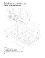
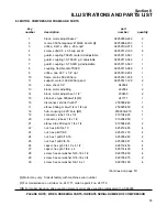
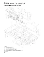
Page 60: ...Section 8 ILLUSTRATIONS AND PARTS LIST 54 8 3 MOTOR COMPRESSOR FRAME AND PARTS 02250140 989R01...
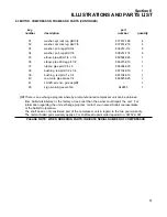
Page 62: ...Section 8 ILLUSTRATIONS AND PARTS LIST 56 8 3 MOTOR COMPRESSOR FRAME AND PARTS 02250140 989R01...
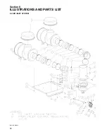
Page 64: ...Section 8 ILLUSTRATIONS AND PARTS LIST 58 8 4 AIR INLET SYSTEM 02250140 990R02...
Page 66: ...Section 8 ILLUSTRATIONS AND PARTS LIST 60 8 4 AIR INLET SYSTEM 02250140 990R02...
Page 68: ...Section 8 ILLUSTRATIONS AND PARTS LIST 62 8 5 FLUID COOLING SYSTEM AIR COOLED 02250140 994R00...
Page 70: ...Section 8 ILLUSTRATIONS AND PARTS LIST 64 8 5 FLUID COOLING SYSTEM AIR COOLED 02250140 994R00...
Page 72: ...Section 8 ILLUSTRATIONS AND PARTS LIST 66 8 6 AIR PIPING SYSTEM AIR COOLED 02250140 992R01...
Page 74: ...Section 8 ILLUSTRATIONS AND PARTS LIST 68 8 6 AIR PIPING SYSTEM AIR COOLED 02250140 992R01...
Page 76: ...Section 8 ILLUSTRATIONS AND PARTS LIST 70 02250140 993R01 8 7 FLUID PIPING SYSTEM AIR COOLER...
Page 78: ...Section 8 ILLUSTRATIONS AND PARTS LIST 72 02250140 993R01 8 7 FLUID PIPING SYSTEM AIR COOLER...
Page 80: ...Section 8 ILLUSTRATIONS AND PARTS LIST 74 02250140 991R00 8 8 SUMP AND PARTS...
Page 82: ...Section 8 ILLUSTRATIONS AND PARTS LIST 76 02250140 991R00 8 8 SUMP AND PARTS...
Page 84: ...Section 8 ILLUSTRATIONS AND PARTS LIST 78 8 9 SULLICON CONTROL 02250134 158R00...
Page 86: ...Section 8 ILLUSTRATIONS AND PARTS LIST 80 8 10 COMPRESSOR ACTUATOR...
Page 88: ...Section 8 ILLUSTRATIONS AND PARTS LIST 82 8 11 PNEUMATIC CONTROLS 02250140 996R00...
Page 90: ...Section 8 ILLUSTRATIONS AND PARTS LIST 84 8 11 PNEUMATIC CONTROLS 02250140 996R00...
Page 92: ...Section 8 ILLUSTRATIONS AND PARTS LIST 86 8 11 PNEUMATIC CONTROLS 02250140 996R00...
Page 94: ...Section 8 ILLUSTRATIONS AND PARTS LIST 88 8 12 CONTROL BOX SOLID STATE 02250122 005R04...
Page 96: ...Section 8 ILLUSTRATIONS AND PARTS LIST 90 8 13 CONTROL BOX FULL VOLTAGE 02250122 511R04...
Page 98: ...Section 8 ILLUSTRATIONS AND PARTS LIST 92 8 14 CONTROL BOX WYE DELTA 02250122 516R08...
Page 100: ...Section 8 ILLUSTRATIONS AND PARTS LIST 94 8 15 ENCLOSURE AIR COOLED 02250140 995R00...
Page 102: ...Section 8 ILLUSTRATIONS AND PARTS LIST 96 8 15 ENCLOSURE AIR COOLED 02250140 995R00...
Page 104: ...Section 8 ILLUSTRATIONS AND PARTS LIST 98 8 16 DECAL GROUP...
Page 106: ...Section 8 ILLUSTRATIONS AND PARTS LIST 100 8 16 DECAL GROUP...
Page 108: ...Section 8 ILLUSTRATIONS AND PARTS LIST 102 8 16 DECAL GROUP...
Page 110: ...Section 8 ILLUSTRATIONS AND PARTS LIST 104 8 17 DECAL LOCATIONS...
Page 112: ...Section 8 ILLUSTRATIONS AND PARTS LIST 106 8 18 DECAL LOCATIONS ENCLOSURE...
Page 114: ...Section 8 ILLUSTRATIONS AND PARTS LIST 108 8 19 DECAL LOCATIONS CONTROL BOX...
Page 117: ...111 NOTES...

