Section 2
DESCRIPTION
9
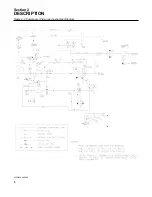
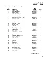
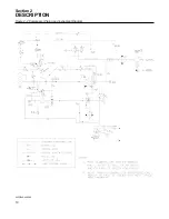
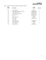
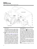
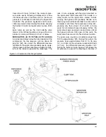
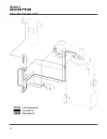
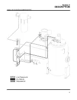
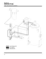
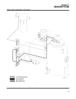
Figure 2-2 Compressor Piping and Instrument Diagram
key
part
number
description
number
quantity
1
filter, 18” air inlet
25006-718
2
2
valve, inlet butterfly 10”
02250128-060
1
3
control, sullicon 32
011682-003
1
4
valve, min press chk 4”
02250141-088
1
5
valve, ball 1/2”npt
047117
1
6
valve, diff. press. reg. 1/4” npt
406929
1
7
valve, solenoid 1/4” 3-way 115 vac
02250125-657
2
8
sep, wtr d-h 4”npt
02250111-106
1
9
orifice .031
02250125-774
1
10
valve, blowdwon 1” nc 2-way
409783
2
11
silencer, air 3/8”
040758
6
12
valve, relief 2” (160#)
02250132-162
1
13
element, primary
02250126-325
1
14
orifice .094
02250125-776
1
15
glass sight 1/4”
02250126-129
2
16
strainer, v-type 3000 psi 1/4”
02250117-782
2
17
trap, automatic
042034
1
18
tank, fluid sep.
02250129-137
1
19
unit, compressor 32 series
1
20
element, secondary
02250126-331
1
21
probe, 100 ohm rtd
02250044-985
3
22
transducer, press. 0-250psi n4
02250078-933
4
23
reservoir, air 415 cu.in.
242221
1
24
valve, ball 3/4”
02250125-221
1
25
cooler, air
02250122-215
1
26
filter, fluid
02250121-638
2
27
gauge, pressure
02250117-009
2
28
cooler, fluid
02250122-217
1
29
pump, oil system
250018-782
1
30
valve,drain-self close 1/8”npt
041111
1
31
valve, oil stop 2.5”
02250122-004
1
32
switch, vac 22” w.c. n4
02250078-249
1
33
vlv, press rlf 1/2”npt 150psig
02250092-138
1
34
glass, fluid level 1”
041327
1
35
valve, press reg
408275
1
(Continued on page 11)
Summary of Contents for LS-32
Page 6: ...NOTES...
Page 14: ...Section 2 DESCRIPTION 8 Figure 2 2 Compressor Piping and Instrument Diagram 02250140 998R02...
Page 16: ...Section 2 DESCRIPTION 10 Figure 2 2 Compressor Piping and Instrument Diagram 02250140 998R02...
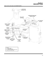
Page 21: ...Section 2 DESCRIPTION 15 Figure 2 5A Control System KEY COMPONENTS...
Page 22: ...Section 2 DESCRIPTION 16 Figure 2 5B Control System START...
Page 23: ...Section 2 DESCRIPTION 17 Figure 2 5C Control System MODULATION...
Page 24: ...Section 2 DESCRIPTION 18 Figure 2 5D Control System UNLOAD...
Page 25: ...Section 2 DESCRIPTION 19 Figure 2 5E Control System FULL LOAD...
Page 28: ...Section 3 SPECIFICATIONS 22 Figure 3 2 Identification LS 32 Air cooled 02250140 997R01...
Page 32: ...Section 5 SUPERVISOR CONTROLLER 26 Figure 5 1 Supervisor Control Panel...
Page 44: ...38 NOTES...
Page 56: ...50 NOTES...
Page 59: ...53 NOTES...
Page 60: ...Section 8 ILLUSTRATIONS AND PARTS LIST 54 8 3 MOTOR COMPRESSOR FRAME AND PARTS 02250140 989R01...
Page 62: ...Section 8 ILLUSTRATIONS AND PARTS LIST 56 8 3 MOTOR COMPRESSOR FRAME AND PARTS 02250140 989R01...
Page 64: ...Section 8 ILLUSTRATIONS AND PARTS LIST 58 8 4 AIR INLET SYSTEM 02250140 990R02...
Page 66: ...Section 8 ILLUSTRATIONS AND PARTS LIST 60 8 4 AIR INLET SYSTEM 02250140 990R02...
Page 68: ...Section 8 ILLUSTRATIONS AND PARTS LIST 62 8 5 FLUID COOLING SYSTEM AIR COOLED 02250140 994R00...
Page 70: ...Section 8 ILLUSTRATIONS AND PARTS LIST 64 8 5 FLUID COOLING SYSTEM AIR COOLED 02250140 994R00...
Page 72: ...Section 8 ILLUSTRATIONS AND PARTS LIST 66 8 6 AIR PIPING SYSTEM AIR COOLED 02250140 992R01...
Page 74: ...Section 8 ILLUSTRATIONS AND PARTS LIST 68 8 6 AIR PIPING SYSTEM AIR COOLED 02250140 992R01...
Page 76: ...Section 8 ILLUSTRATIONS AND PARTS LIST 70 02250140 993R01 8 7 FLUID PIPING SYSTEM AIR COOLER...
Page 78: ...Section 8 ILLUSTRATIONS AND PARTS LIST 72 02250140 993R01 8 7 FLUID PIPING SYSTEM AIR COOLER...
Page 80: ...Section 8 ILLUSTRATIONS AND PARTS LIST 74 02250140 991R00 8 8 SUMP AND PARTS...
Page 82: ...Section 8 ILLUSTRATIONS AND PARTS LIST 76 02250140 991R00 8 8 SUMP AND PARTS...
Page 84: ...Section 8 ILLUSTRATIONS AND PARTS LIST 78 8 9 SULLICON CONTROL 02250134 158R00...
Page 86: ...Section 8 ILLUSTRATIONS AND PARTS LIST 80 8 10 COMPRESSOR ACTUATOR...
Page 88: ...Section 8 ILLUSTRATIONS AND PARTS LIST 82 8 11 PNEUMATIC CONTROLS 02250140 996R00...
Page 90: ...Section 8 ILLUSTRATIONS AND PARTS LIST 84 8 11 PNEUMATIC CONTROLS 02250140 996R00...
Page 92: ...Section 8 ILLUSTRATIONS AND PARTS LIST 86 8 11 PNEUMATIC CONTROLS 02250140 996R00...
Page 94: ...Section 8 ILLUSTRATIONS AND PARTS LIST 88 8 12 CONTROL BOX SOLID STATE 02250122 005R04...
Page 96: ...Section 8 ILLUSTRATIONS AND PARTS LIST 90 8 13 CONTROL BOX FULL VOLTAGE 02250122 511R04...
Page 98: ...Section 8 ILLUSTRATIONS AND PARTS LIST 92 8 14 CONTROL BOX WYE DELTA 02250122 516R08...
Page 100: ...Section 8 ILLUSTRATIONS AND PARTS LIST 94 8 15 ENCLOSURE AIR COOLED 02250140 995R00...
Page 102: ...Section 8 ILLUSTRATIONS AND PARTS LIST 96 8 15 ENCLOSURE AIR COOLED 02250140 995R00...
Page 104: ...Section 8 ILLUSTRATIONS AND PARTS LIST 98 8 16 DECAL GROUP...
Page 106: ...Section 8 ILLUSTRATIONS AND PARTS LIST 100 8 16 DECAL GROUP...
Page 108: ...Section 8 ILLUSTRATIONS AND PARTS LIST 102 8 16 DECAL GROUP...
Page 110: ...Section 8 ILLUSTRATIONS AND PARTS LIST 104 8 17 DECAL LOCATIONS...
Page 112: ...Section 8 ILLUSTRATIONS AND PARTS LIST 106 8 18 DECAL LOCATIONS ENCLOSURE...
Page 114: ...Section 8 ILLUSTRATIONS AND PARTS LIST 108 8 19 DECAL LOCATIONS CONTROL BOX...
Page 117: ...111 NOTES...


