background image

Appendix C. Upgrading Controller Software

EK–SMRAB–IG. B01

C–7

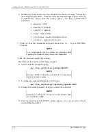
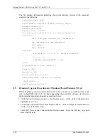
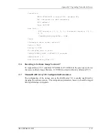
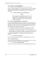
C.4.1  Downloading the Software

To download the new software, follow these steps:

1.  Insert the distribution CD-ROM containing the binary file of the new software image

into a CD-ROM drive of a computer connected to the RAID Array controller.

2.  Copy the firmware image from the CD-ROM software directory (\firmware\v3.1)

into a temporary directory on the system disk.

3.  Start the terminal program with the communications settings as specified above.

4. Press 

the 

Enter key to get to the 

HSZ20>

 prompt.

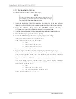
5.  Invoke the CLCP utility, at the 

HSZ20>

 prompt, type:


run clcp

.


Select an option from the following list:


Code Load and Patch Utility Main Menu

0:  Exit

1:  Enter Code LOAD utility

2:  Enter Code PATCH utility


Enter option number (0..2) ? 1

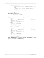
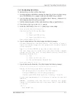
6. Type: 

1 and press Return. The utility displays the following message:

You have selected the Code Load Utility.  This utility is used to

load a new software image into the program card currently inserted

in the controller.

Type ^Y or ^C (then RETURN) at any time to abort code load.

The code image may be loaded using SCSI Write Buffer commands

through the SCSI Host Port, or using KERMIT protocol through the

Maintenance Terminal Port.

0:  Exit

1:  Enter the SCSI Host Port

2:  Use the Maintenance Terminal Port

Enter option number (0..2) [0] ? 2

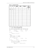
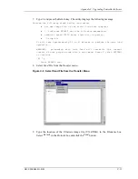
7. Type: 

2

 and press the Return key. The utility displays the following message:

---------------------------------------------

Perform the following steps before continuing:

*get new image file on the serial line host computer

*configure KERMIT with the following parameters:

 terminal speed 19200 baud, eight bit, no parity, 1 stop bit

It will take approximately 35 to 45 minutes to perform the code load

operation.

WARNING:  proceeding with Code Load will overwrite the current

content of your program code with a new image. Enter Y (then RETURN)

to continue

 [N] ? y

Start KERMIT now…

Summary of Contents for EK-SMRAB-IG

Page 1: ...Getting Started RAID Array 310 V3 1 for HP UX Installation Guide EK SMRAB IG B01 Digital Equipment Corporation Maynard Massachusetts...

Page 2: ...ment Corporation makes no representation that the use of its products in the manner described in this publication will not infringe on existing or future patent rights nor do the descriptions containe...

Page 3: ...er Configuration 2 1 Introduction 2 1 2 2 What is the CLI 2 2 2 3 Accessing the CLI 2 2 2 3 1 Start the Communications Program 2 2 2 3 2 Establish the Connection with the Controller 2 2 2 4 Show Initi...

Page 4: ...NT 3 51 Procedures C 5 C 4 1 Downloading the Software C 7 C 5 Firmware Upgrade Procedures for Windows 95 and Windows NT 4 0 C 10 C 5 1 Downloading the Software C 11 C 6 Reverting to Software Image Ver...

Page 5: ...ubsystem CLI Serial Connector 1 7 1 6 StorageWorks SCSI Bus Port and Default SCSI ID Assignment 1 10 2 1 Distribution Example 2 6 C 1 Select Send Binary Files from the Transfers Menu C 8 C 2 Select th...

Page 6: ......

Page 7: ...following revision history lists all revisions of this publication and their effective dates The publication part number is included in the Revision Level column with the last entry denoting the late...

Page 8: ......

Page 9: ...ems Installing the StorageWorks RAID Array 310 Subsystem requires a general understanding of UNIX system administration and product installation procedures Document Structure This guide contains the f...

Page 10: ...d Console CC Client on each of your client systems Appendix A Configuration Records Blank Forms This appendix contains a copy of the tables used in Chapter 2 to record the configuration of your system...

Page 11: ...space type Text italic type For emphasis and manual titles Represents the HP UX system prompt Do not type it as part of information given here as to be input by the user In addition the following nami...

Page 12: ......

Page 13: ...teps required to install a RAID Array 310 Subsystem See the specified chapters for detailed procedures Depending upon your specific configuration requirements you may not need to perform all the tasks...

Page 14: ...FWD SCSI adapters Built in HP PB 28696A GSC A4107A HSC A4107A HSC A2969A The associated system hardware manual Appropriate tools to service your computer The HP UX operating system V10 01 or higher If...

Page 15: ...skside Subsystem Hardware User s Guide EK SMCPL UG The StorageWorks RAID Array 310 Subsystem Serial cabling kit see Section 1 7 1 for connecting the maintenance port of the controller to the serial po...

Page 16: ......

Page 17: ...ollowing seven major steps Unpacking and setting up the mechanical configuration Chapter 1 Connecting ac power and recharging the controller cache battery Chapter 1 Making the serial interface connect...

Page 18: ...n area NOTE Before unpacking the equipment inspect the shipping carton for signs of external damage Report any damage to the local carrier and to your reseller Refer to Figure 1 2 and complete the fol...

Page 19: ...ration Preparing the RAID Array 310 for operation involves the following procedures 1 Mounting the base as described in Section 1 5 2 Mounting the door 3 Installing the disk Storage Building Blocks SB...

Page 20: ...supplies which provide redundant power to the RAID Array 310 Each supply is equipped with an ac power receptacle for connection to a 125 or 250 Vac power source The power supply automatically senses a...

Page 21: ...er Cords Country Length Order No Australia 2 5 m BN19H 2E C Europe 2 5 m BN19C 2E Denmark 2 5 m BN19K 2E India 2 5 m BN19S 2E Ireland 2 5 m BN19A 2E Israel 2 5 m BN18L 2E Italy 2 5 m BN19M 2E Japan 2...

Page 22: ...Getting Started RAID Array 310 V3 1 for HP UX 1 6 EK SMRAB IG B01 Figure 1 4 Subsystem AC Power Receptacles...

Page 23: ...ts 1 stop bit and no parity Figure 1 5 Subsystem CLI Serial Connector 1 7 1 Cabling Kit Locate and open the cabling kit that was shipped with your RAID Array 310 subsystem The kit should contain the f...

Page 24: ...H8571 J connectors 1 7 3 Terminal Connection Refer to your terminal documentation for terminal setup instructions 1 7 4 Setting up the Serial Line using SAM Start the System Administrator Utility SAM...

Page 25: ...and Modems section in HP manual Installing Peripherals 1 7 5 CLI Serial Interface Verification Entering the CLI command SHOW THIS_CONTROLLER causes the controller to display its description banner ve...

Page 26: ...result in the loss of data We recommend that you take this opportunity now to recharge the batteries This is accomplished by doing the following Apply power to the controller by pressing the power swi...

Page 27: ...cribe this process The Command Console GUI runs on an Intel based PC with either Windows 95 or Windows NT It can be used via the serial interface to the RAID Array 310 or by using a networked connecti...

Page 28: ...erminal Refer to Section 1 7 in Chapter 1 of this guide Connecting the CLI Interface for a description of how to connect the maintenance terminal to the RAID 310 controller if necessary 2 3 1 Start th...

Page 29: ...Y STATE CODE 85780 CONFIGURATION BACKUP DISABLED Examine the display to verify the following information Controller SCSI target number is recommended to be set to 0 If the target number is not 0 use t...

Page 30: ...License Key page that is provided in the subsystem documentation package Configuration backup can be enabled or disabled Configuration backup will keep RAID Array controller configuration stored on d...

Page 31: ...ubsystem Please be patient add disk100 1 0 0 add disk110 1 1 0 add disk120 1 2 0 add disk130 1 3 0 add disk200 2 0 0 add disk210 2 1 0 add disk220 2 2 0 Config Normal Termination In the previous examp...

Page 32: ...communications LUN as described in section 2 7 or Appendix D depending on the type of storageset you want to use If an HP 800 system is used with a HP PB bus SCSI adapter HP 28696A a special SCSI dri...

Page 33: ...e controller will select a chunksize that works well for most site requirements Refer to the RAID Array 310 Configuration and Maintenance Guide for the specific default chunksize When no chunksize is...

Page 34: ...orageset named RAIDS0 D0 means SCSI ID 0 LUN 0 which may be different for your particular situation This new unit can now by used as a communications LUN during the installation of the agent as descri...

Page 35: ...e sys tem to interface with the RAID Array 310 FWD SCSI connectors on add on or existing host adapters are labeled on the rear panel of your 9000 Series computer Do not connect or disconnect the SCSI...

Page 36: ...Driver Required The device drivers you will need for the StorageWorks RAID Array Controller are listed in Table 3 1 This driver is software configurable and is a standard part of the HP UX operating...

Page 37: ...i3 CLAIMED INTERFACE HP 28696A Fast Wide SCSI Inter face On a Series 700 System C D J or K Class machine type ioscan f d c720 The output from this command will be similar to Class I H W Path Driver S...

Page 38: ...by the CLI in Chapter 2 Creating an Initial Configuration Using the Command Line Interpreter 3 2 5 Reboot the System and Verify the Successful Installation NOTE Before proceeding the RAID Array Contro...

Page 39: ...n in the event of a failure Local notification can be made via E mail and or the syslog facility Remote notification can be made via SNMP messages to an SNMP Monitor The CC Client is not required for...

Page 40: ...interpreter CLI software to create one Subsystems without at least one volume are invisible to Agent and the host operating system The fastest and most user friendly method of configuring an Agent is...

Page 41: ...install should be done the session will continue as follows This script will make changes to several system level files and install all application files You MUST be root to effect these changes Curre...

Page 42: ...the installation and configuration script Example opt steam bin stgwrks sh Next install the Agent type 2 the ENTER key After the copyright select install agent 2 from the main menu After the copyright...

Page 43: ...ault area opt Type the ENTER key Installing the STEAM Agent in opt steam Is this okay Y n Type y then the ENTER key Adding an entry to etc services for the Client using port 4998 Is this OK Y n Specif...

Page 44: ...a system error log Remote notification is provided to the command console for display or paging Users that wish to only have local HP platform notification can disable messages to the client by enter...

Page 45: ...e ENTER key Adding a storage subsystem Enter subsystem host name Enter the subsystem name e g hp_ storage1 and then press the ENTER key Enter the character special file name for accessing the storage...

Page 46: ...ype y then the ENTER key Would you like to add another user y N Type n then the ENTER key Authorized mail notification list Username Notification Level Hit RETURN to continue The STEAM Agent package h...

Page 47: ...If STEAM Agent is Running is displayed enter y to terminate the Agent Then repeat the menu selection and enter y to start the Agent If STEAM Agent is Not Running is displayed enter y to start the Agen...

Page 48: ...Uninstalling CC Agent You can remove any Agent program using the uninstall program You have two options to remove an Agent Run the Agent configuration script on the host and Select Option 5 Run the co...

Page 49: ...the device on your system Editing the etc checklist file if you want this device mounted each time you boot the system NOTE If changes are made on the RAID Array 310 before they are removed from the s...

Page 50: ......

Page 51: ...nsole Plus must be purchased Install a copy of the Command Console Client program on each of the Intel based systems on your network from which you want to configure or monitor a StorageWorks RAID Arr...

Page 52: ...Place the CD in the CD ROM drive 2 Select My Computer 3 Double click on the CD ROM drive icon 4 Double click on the client icon 5 Double click on install bat icon 6 Follow the instructions in the setu...

Page 53: ...Configuration Records Blank Forms This appendix contains copies of the two tables used in Chapter 2 to record the configuration of your sys tem If additional copies are required these tables can be re...

Page 54: ...Getting Started RAID Array 310 V3 1 for HP UX A 2 EK SMRAB IG B01 Date_____________ LUN Uses...

Page 55: ...Array 310 supports a maximum of four SCSI IDs 4 Avoid configuring multiple mirrorsets with the first members being on the same port That is use add mirrorset m1 disk100 disk200 add mirrorset m2 disk21...

Page 56: ......

Page 57: ...nd HSZ20 show this_controller full Record the following information in the blanks below SCSI Targets Preferred Targets Cache Flush Timer Cache Policy and Host Functionality Mode Fill in the blanks bel...

Page 58: ...D100 S28 Switches RUN NOWRITE_PROTECT READ_CACHE WRITEBACK_CACHE MAXIMUM_CACHED_TRANSFER_SIZE 32 State ONLINE to this controller Not reserved PREFERRED_PATH THIS_CONTROLLER Size 20547350 blocks D200 M...

Page 59: ...WXRC show storagesets full The controller responds with a display similar to that shown below Name Storageset Uses Used by S28 stripeset DISK130 D100 DISK220 Switches CHUNKSIZE 256 blocks State NORMAL...

Page 60: ...ageset Table Table C 2 The first row shows how to record for S28 of the sample NOTE Not all column headings apply to all storagesets Table C 2 Storageset Table NAM E STORAGE SET USES USED BY POLICY CO...

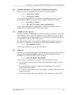
Page 61: ...r It takes approximately 40 minutes to download the new software image at 19200 baud To begin upgrading the controller software start and setup the terminal emulation program as specified below NOTE I...

Page 62: ...lick OK NOTE It is recommended that the window be maximized while upgrading the firmware or when running other diagnostics Click OK when you complete the settings Press the Enter key and the default p...

Page 63: ...lity displays the following message You have selected the Code Load Utility This utility is used to load a new software image into the program card currently inserted in the controller Type Y or C the...

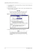
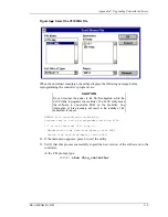
Page 64: ...hown in Figure B 1 CAUTION You must use a binary transfer mode Failure to use a binary transfer mode will result in corruption of the controller software Figure C 1 Select Send Binary Files from the T...

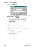
Page 65: ...the software in non volatile RAM on the controller Any interruption of this procedure will result in the inability of the subsystem to reboot KERMIT file transferred successfully Program card is bein...

Page 66: ...che 16 megabyte write cache version 2 Cache is GOOD Battery is GOOD No unflushed data in cache CACHE_FLUSH_TIMER DEFAULT 10 seconds CACHE_POLICY A Host Functionality Mode A C 5 Firmware Upgrade Proced...

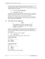
Page 67: ...ler will provide a list of available commands NOTE For a list of additional command options type the command followed by a space plus a 8 Click File at the menu bar Choose Save to save the configurati...

Page 68: ...cations settings as specified above 4 Press the Enter key to get to the HSZ20 prompt 5 Invoke the CLCP utility at the HSZ20 prompt type run clcp Select an option from the following list Code Load and...

Page 69: ...baud eight bit no parity 1 stop bit It will take approximately 35 to 45 minutes to perform the code load operation WARNING proceeding with Code Load will overwrite the current content of your program...

Page 70: ...red successfully Program card is being reprogrammed with new file Do not interrupt this step Manufacturer code read from memory card 8989 Device Code read from memory card bdbd 10 If the main menu app...

Page 71: ...ata in cache CACHE_FLUSHED_TIMER DEFAULT 10 seconds CACHE_POLICY A Host Functionality Mode A C 6 Reverting to Software Image Version 2 7 To request release V2 7 substitute V27Z IMG for V31Z IMG in the...

Page 72: ......

Page 73: ...efined Performance of your STRIPEsets will be optimized if each STRIPEset includes disks from different buses as shown in Figure 2 1 in Chapter 2 The example above contains disks from different buses...

Page 74: ...eates LUN 0 for controller target ID 1 specified earlier with the SET THIS_CONTROLLER command D 1 3 Set Writeback Cache The final step in creating a STRIPEset is to enable the writeback cache A single...

Page 75: ...writeback cache A single CLI command enables that feature for the entire MIRRORset HSZ20 SET D200 WRITEBACK_CACHE Where D200 represents the host logical unit of the MIRRORset created above D 3 Create...

Page 76: ...e unit number is a one or three digit number preceded by D such as D0 or D102 The unit number is made of the controller s target ID and the Logical Unit LUN of the striped MIRRORset for the target Eac...

Page 77: ...led disk as soon as possible For maximum availability you should keep at least one drive in the spareset The Spareset always exists in the controller configuration even if there are no drives assigned...

Page 78: ...o longer transportable Additional metadata is written on it when it is moved from the spareset into a RAIDset or MIRRORset D 7 Verify and Record Your Configuration NOTE Your configuration may be saved...

Page 79: ...Appendix D Configuring STRIPEsets MIRRORsets and Striped MIRRORsets EK SMRAB IG B01 D 7 Date__________________ LUN Uses...

Page 80: ...D200 DISK210 RAIDS1 raidset DISK100 D0 DISK200 DISK110 FAILEDSET failedset Configuration Example 2 Name Storageset Uses Used by MIRSTR1 stripeset MIRROR3 D300 MIRROR4 MIRROR3 mirrorset DISK100 MIRSTR...

Page 81: ...Appendix D Configuring STRIPEsets MIRRORsets and Striped MIRRORsets EK SMRAB IG B01 D 9 Date__________________ Name Storageset Uses Used By...

Page 82: ...xample 1 Name Type Port Targ Lun Used by DISK100 disk 1 0 0 RAIDS1 DISK110 disk 1 1 0 RAIDS1 DISK120 disk 1 2 0 MIRROR1 DISK130 disk 1 3 0 STRIPE1 DISK200 disk 2 0 0 RAIDS1 DISK210 disk 2 1 0 MIRROR1...

Page 83: ...Appendix D Configuring STRIPEsets MIRRORsets and Striped MIRRORsets EK SMRAB IG B01 D 11 Date__________________ Name Type Port Targ Lun Used By...

Page 84: ......

Reviews: