


© 2021 Staheli West
47
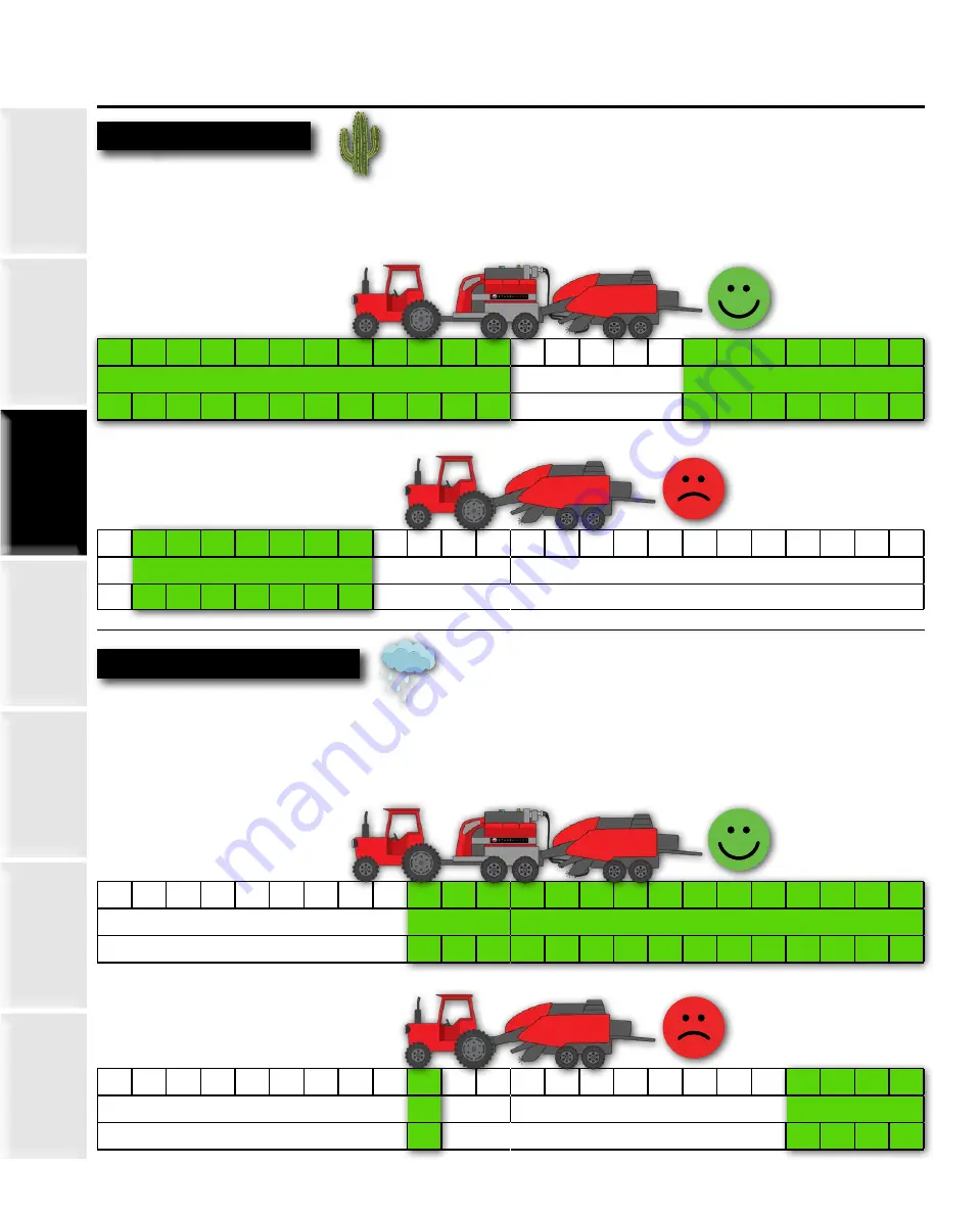
Common Operating Times
In dry climates, DewPoint operators normally start baling in the late evening and bale through the night,
adjusting steam for the changing dew conditions. If necessary, the operator can bale for 24 hours straight, as
long as conditions don’t get too wet or too hot, causing internal bale temperatures to exceed 140° F.
Dry Climates
Wetter Climates
In
wet climates, DewPoint operators normally start baling in the morning as soon as the dew burns off and the
hay is dry enough to start baling. Operators often bale through the rest of the day, as long as the internal bale
temperatures don’t exceed 140° F. They often bale into the evening until the windrows become too saturated
with dew.
1
2
3
4
5
6
7
8
9 10 11 12 1
2
3
4
5
6
7
8
9 10 11 12
AM
PM
Often too hot
1
2
3
4
5
6
7
8
9 10 11 12 1
2
3
4
5
6
7
8
9 10 11 12
AM
PM
Not enough dew / moisture / often too hot
1
2
3
4
5
6
7
8
9 10 11 12 1
2
3
4
5
6
7
8
9 10 11 12
AM
PM
Often too wet
1
2
3
4
5
6
7
8
9 10 11 12 1
2
3
4
5
6
7
8
9 10 11 12
AM
PM
Often too wet
Not enough dew / moisture
Summary of Contents for DewPoint 331
Page 213: ... 2021 Staheli West 204 Notes ...
Page 214: ... 2021 Staheli West 205 Notes ...
Page 215: ... 2021 Staheli West 206 Notes ...