


Getting Started
Procedure 5: Perform Cable Connections
26
|
Getting Started with Spirent TestCenter
Procedure 5: Perform Cable Connections
This section explains how to connect cables to the connectors. We recommend that you
complete Procedures 5 through 11 in this guide before you connect to an application or
device under test (Procedure 12).
•
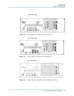
Panel connectors on the SPT-N4U are shown in
.
•
Panel connectors on the SPT-N11U and SPT-N12U are shown in
.
•
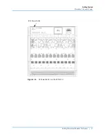
Panel connectors on the SPT-C50 are shown in
.
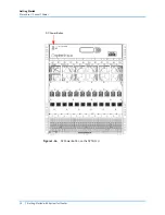
•
Panel Connectors on the SPT-C50-S2-RX are shown in
.
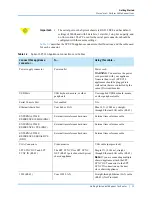
Notes: •
For complete installation and setup information for the Spirent C1 or the
PX3/DX3-QSFP-DD-8 appliances, refer to the installation documentation
that is included in your appliance shipment.
•
Refer to FAQ18073 for information about External Time Reference (ETR)
methods you can use to sync multiple remote chassis. Go to the Customer
Service Center (CSC) (
) and type
FAQ18073
in
the
Search
box. Press Enter.
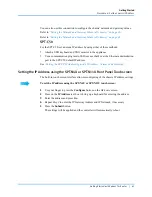
Figure 1-2.
SPT-N4U Front Panel
Removable Hard
Drive Tray
LEDs for Chassis
Connection Status
External Time Reference Connectors
DVI-I Connector
USB Ports
Ethernet Admin
Port
Multiple Chassis
Connection Ports
Note
: The two (2) Power Cord
Connectors are on the back of the
chassis (not shown). Depending on the
model, there will be one (1) or two (2).


