background image

3   |   Connections and Setup

STp.1120n User’s Guide

42

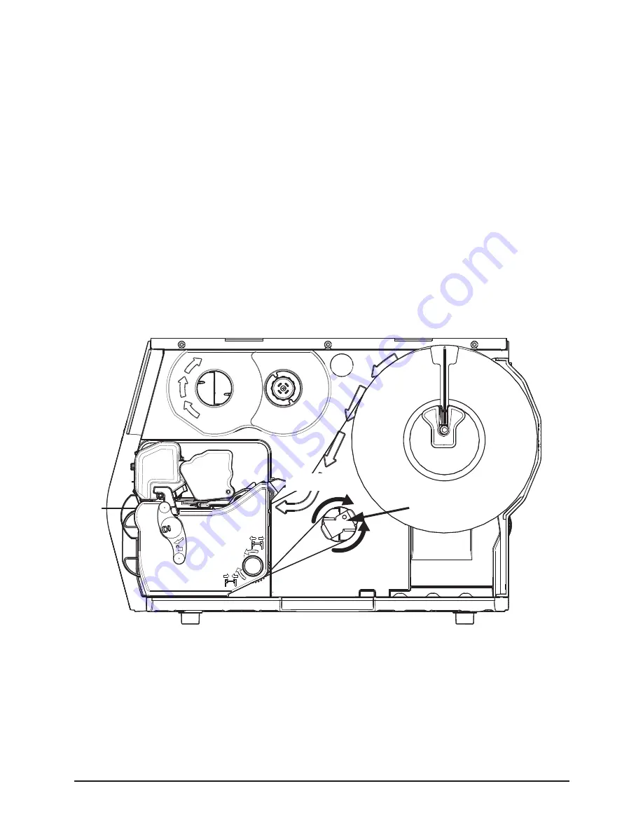
Optional Rewinder

The rewinder is designed to rewind in either direction but the direction must be set 
through the menu.

Note: 

Either the peel plate or the rewinder plate must be installed.

Installation of Media

1. Route the media through the platen carriage assembly.

Note: 

Follow the instructions for the installed media hanger.

2. Route the media under the platen carriage and around the rewinder shaft.

3. Remove the metal clasp and wind the media around the rewinder shaft in the 

desired direction.

Figure: 3 - 36 Rewinder

4. Insert the edge of the media into one of the two grooves on the rewinder shaft.

Counter Clockwise

Clockwise

Metal Clasp

Summary of Contents for STP.1120N

Page 1: ...STp 1120n User s Guide...

Page 2: ......

Page 3: ...STp 1120n User s Guide Source Technologies LLC 2910 Whitehall Park Drive Charlotte NC 28273 Phone 1 800 922 8501 Fax 704 969 7595 www sourcetech com...

Page 4: ......

Page 5: ...ty or liability for the accuracy or completeness of or consequences arising from such information This document is intended for informational purposes only Mention of trade names or commercial product...

Page 6: ......

Page 7: ...pment Including Electrical Business Equipment CAN CSA C22 2 No 60950 1 Safety of Information Technology Equipment Including Electrical Business Equipment European Council Directive 2004 108 EC EMC Dir...

Page 8: ...ack for recycling when this ultimately becomes waste Instructions to both EU customers and recyclers treatment facilities wishing to obtain disassembly information are provided by following the link b...

Page 9: ...s and Setup Connections 11 Media Loading 11 Media Hanger Self Centering 12 Media Hanger Cantilever 19 Media Hub 27 Installing Ribbon 34 Configuring Media and Ribbon Settings 39 Optional Rewinder 42 To...

Page 10: ...Sensor 124 Cleaning the Label Low Sensor 124 Cleaning the Printhead 124 Cleaning the Cutter 125 6 Troubleshooting Errors 127 Warnings 128 Troubleshooting 128 Troubleshooting Print Quality 131 7 Terms...

Page 11: ...rsonnel Any on site assembly required during the installation process must be performed by properly trained and qualified service personnel The product must be connected to a properly grounded and app...

Page 12: ...1 Safety STp 1120n User s Guide 2 This product must be connected to a properly grounded and appropriately rated AC receptical Figure 1 1 Caution Hot The printhead heats during printing Do not touch...

Page 13: ...he following illustrations show some of the features and available options for the STp 1120n near edge printer Figure 2 1 Front View 1 2 3 4 5 6 1 Touchscreen Control Panel 2 Power LED 3 Error LED 4 C...

Page 14: ...ure 2 2 Rear View 1 2 3 4 5 6 7 8 9 1 Wireless Antenna Optional 2 Reset Switch 3 GPIO Port Optional 4 Serial Port Optional 5 Ethernet Network Port 6 USB Port 7 Power Switch 8 Fanfold Media Slot 9 Rear...

Page 15: ...3 Media 4 Media Hanger 5 Printhead Carriage Assembly 6 Printhead Latch 7 Printhead Latch Lever 8 Rear Fanfold Media Access Slot 9 Platen Carriage Assembly 10 Media Width Guide Adjustment Knob 11 Boun...

Page 16: ...or the top of the form Tear Bar Removable bar for tearing off gapped or continuous media Media Back Feed Capable of backing up at least 1 0 for near edge printhead Control panel LED backlit color QVG...

Page 17: ...Printer Language HP PJL HP PCL5e HP GL 2 and HP XL printer languages with auto language select and extensions for barcode capabilities Bi directional communications capability is also supported Inter...

Page 18: ...aging material may be available from your reseller Printer Power Cord Driver CD Product documentation not included on the CD Accessories Options Additional items that may be required include the follo...

Page 19: ...ration Utility Minimum System Requirements Height Width Depth Weight 11 9 in 30 3 cm 10 8 in 27 4 cm 18 7 in 47 5 cm 41 lbs 19 kg Temperature Humidity Operating 5 C to 40 C 20 to 80 Storage 20 C to 60...

Page 20: ...ms Windows XP x86 x64 Windows Vista x86 x64 Windows 7 x86 x64 Windows 2003 Server x86 x64 Windows 2008 Server x86 x64 Windows 2003 Server R2 x86 x64 RAM 256MB Hard Drive Space 5MB Minimum Screen Resol...

Page 21: ...back of the printer 3 Connect the AC power cord to AC utility power Data Printer data connectivity can be accomplished by the following standard or optional interfaces USB Ethernet Network Serial Opti...

Page 22: ...ring Figure 3 1 Self Centering Media Hanger Media core size 3 76 199mm Media roll diameter Maximum 8 Media Roll Width 1 Inside media adjustment lever 2 Paper Low Sensor Optional 3 Self centering media...

Page 23: ...ications 5 H x 1 W Note Ensure there is no tape or adhesive residue on the media roll Installing Media for the First Time 1 Open the media cover 2 Unlock the printhead mechanism by turning the printhe...

Page 24: ...14 3 Center the media adjuster knob and pull it to widen the gap between the two media adjustment levers Figure 3 3 Self Centering Media Hanger from Top 4 Rotate the outside media adjustment lever dow...

Page 25: ...tment lever onto the media hanger Caution Be careful not to damage the outside media adjustment lever Figure 3 5 Media Installation 6 Rotate the outside media adjustment lever upward Figure 3 6 Outsid...

Page 26: ...tween the media adjustment levers and the media roll 8 Rotate the media guide adjustment knob counter clockwise to widen the guides until they are set slightly wider than the width of the media Figure...

Page 27: ...s beyond the pinch roller Figure 3 9 Pinch Roller 11 Rotate the media guide adjustment knob clockwise to tighten the guides Note Ensure the guides are neither too tight nor too loose on the media or p...

Page 28: ...d under the printhead once the printhead carriage assembly has been latched and locked If the media does not automatically load unlatch the printhead assembly and manually feed the media under the pri...

Page 29: ...e 3 12 Cantilever Media Hanger Media Specifications Media core size 3 76 199mm Media roll diameter Maximum 8 Media Roll Width Maximum 4 65 Media thickness 003 to 01 Media dimensions 1 2 3 1 Inside med...

Page 30: ...e there is no tape or adhesive residue on the media roll Installing Media for the First Time 1 Open the media cover 2 Unlock the printhead mechanism by turning the printhead latch lever clockwise abou...

Page 31: ...inside media adjustment lever and position the bottom of the lever to the appropriate width so the media is centered with the printer carriage assembly Figure 3 14 Cantilever Media Adjustment 4 Rotate...

Page 32: ...Rotate the outside media adjustment lever outward Figure 3 15 Cantilever Media Adjustment 6 Gently route the media core over the outside media adjustment lever onto the media hanger Caution Be carefu...

Page 33: ...edia adjustment lever inward towards the media core and rotate the lever upwards to lock in place Figure 3 16 Cantilever Media Adjustment Note Ensure the media roll turns freely There should be 8mm to...

Page 34: ...e adjustment knob counter clockwise to widen the guides until they are set slightly wider than the width of the media Figure 3 17 Media Guide Adjustment Knob 9 Route the media under the bouncer and in...

Page 35: ...s beyond the pinch roller Figure 3 19 Pinch Roller 11 Rotate the media guide adjustment knob clockwise to tighten the guides Note Ensure the guides are neither too tight nor too loose on the media or...

Page 36: ...d automatically feed under the printhead once the printhead carriage assembly has been latched and locked If the media does not automatically load unlatch the printhead carriage and manually feed the...

Page 37: ...a Specifications Media core size 3 76 199 mm standard 1 25 4 mm optional 1 5 38 099 mm optional Media roll diameter Maximum 8 Media roll width Maximum 4 65 Media thickness 003 to 01 1 2 3 4 5 1 Media...

Page 38: ...Note Ensure there is no tape or adhesive residue on the media roll Installing Media for First Time 1 Open the media cover 2 Unlock the printhead mechanism by turning the printhead latch lever clockwi...

Page 39: ...tward using the handle Figure 3 24 Media installation 4 Hold the media hub adjustment lever and place the media core on the core holders 5 Slide the media hub inward using the handle and release the h...

Page 40: ...adjustment knob counter clockwise to widen the guides until they are set slightly wider than the width of the media Figure 3 26 Media Guide Adjustment Knob 7 Route the media under the bouncer and int...

Page 41: ...op 9 While pressing the pinch roller knob rotate the media guide adjustment wheel until the media guide touches the media on both sides Caution Ensure the media guides are neither too tight nor too lo...

Page 42: ...clockwise until the printhead mechanism is locked Figure 3 30 Lock the Printhead Mechanism Note If the media has been installed properly and read by the autoloading sensor it should automatically fee...

Page 43: ...p 1120n User s Guide would be beneficial to feed the media by selecting the Feed button on the main menu to properly set the next label 12 Set the Top of Form sensor Note Refer to the section called S...

Page 44: ...bon should be slightly wider than the print media being used to ensure proper coverage 1 Open the media cover 2 Rotate the printhead latch lever clockwise to unlock and raise the printhead carriage as...

Page 45: ...tall Ribbon 4 Route the ribbon between the ribbon cam roller and the green top of form adjustment lever Note The printer supports both inside ink and outside ink Ensure the ink side faces the media No...

Page 46: ...d Setup STp 1120n User s Guide 36 Caution Do not route the ribbon under the green top of form sensor Figure 3 33 Route Ribbon Inside ink ribbon is shown Cam Roller Top of Form Sensor Adjustment Inside...

Page 47: ...Rewinder Hub Note Roll the ribbon around the ribbon rewinder hub at least five 5 times to ensure it will stay in position 6 Ensure the thermal transfer option is selected through the control panel 7...

Page 48: ...9 Rotate the printhead latch lever counter clockwise to lock the printhead carriage Note Ensure the printhead latch lever has locked the printhead mechanism before printing or the printer will enter a...

Page 49: ...d and enter the appropriate 4 digit code 5 Select the green Accept button to confirm your selection 6 After selecting the Home button select the green Accept button to again confirm your selection or...

Page 50: ...unwinds in a counter clockwise direction CSO ribbon dull side facing outward should be installed where the ribbon unwinds in a clockwise direction If these settings do not match the ribbon type being...

Page 51: ...option appears The options are as follows None Coated In Coated Out 5 Tab to the next screen and enter values for Heat and Heat Balance 6 Tab to the next screen and enter values for Head Pressure and...

Page 52: ...llation of Media 1 Route the media through the platen carriage assembly Note Follow the instructions for the installed media hanger 2 Route the media under the platen carriage and around the rewinder...

Page 53: ...ction 1 Select Menu Basic Printer Mode 2 Select one of the three options Note Upon exiting the utility a prompt will ask the user to accept the changes or reject them Top of Form Sensor This printer i...

Page 54: ...hese include gap mark on top mark on bottom notch and continuous The following are illustrations of the types of supported media but not every supported media is illustrated Please contact your resell...

Page 55: ...Connections and Setup 3 45 STp 1120n User s Guide Figure 3 40 Mark on Top Example Figure 3 41 Mark on Bottom Example Figure 3 42 None...

Page 56: ...5 Select the paper sensor side either inside or outside that correlates with the type of media being used Note For example media types with marks in the middle of the media select Outside Note The LED...

Page 57: ...arriage assembly was removed in the image above The LED sensor pods can be viewed from the front of the printer under the printhead carriage assembly The active sensor pod is lit by an LED Note If the...

Page 58: ...there are no folds or creases in the ribbon 3 Adjust the front ribbon shield to the middle position of the mounting slot Figure 3 44 Ribbon Shield 4 Set the printer to print ten 10 consecutive Qualit...

Page 59: ...to adjust the ribbon plate Figure 3 45 Supply Side Inspection 7 If excessive ripples exist loosen the 3mm cam roller hex head screw enough to allow the cam roller to spin Figure 3 46 Cam Roller 8 Tur...

Page 60: ...kles still appear continue with the adjustment procedure 11 Loosen the ribbon shield adjustment screws 12 While printing test labels slowly adjust the lower shield until the ribbon tension is constant...

Page 61: ...y Caution The media cover will not close with both the cutter and present sensor installed at the same time Caution The printer must be powered off and disconnected from AC utility power prior to the...

Page 62: ...dia plate thumbscrew and the media plate Figure 3 48 Remove Media Plate Note Retain the thumbscrew for cutter installation 3 Align the cutter with the power data connector and install the thumbscrew t...

Page 63: ...just settings in the Adjustments menu Note A negative value moves the cut line toward the current label being printed A positive value moves the cut line toward the next label to be printed Cutter Tra...

Page 64: ...ss otherwise noted The installer should note the following The printer driver files are installed into the Windows print system so when a USB printer is connected or a network printer is added the sys...

Page 65: ...The File Download window is displayed Figure 3 51 File Download Window 4 Select Save and browse to the appropriate location where the file can be saved Note For future reference be sure to note the d...

Page 66: ...tup STp 1120n User s Guide 56 2 Select Software Figure 3 52 Installation Utility Software 3 Select Windows Print Driver and proceed with the installation instructions Figure 3 53 Installation Utility...

Page 67: ...cally or to a network Caution Do not connect a USB cable to the printer at this point 1 Locate the Performance Series Print Driver setup file from the saved location or from the product CD launch 2 Do...

Page 68: ...58 4 Select Install Driver Files Only and then select Next Figure 3 55 Performance Series Install Files Add Printer Selection 5 Browse to the appropriate folder location select the user option and th...

Page 69: ...STp 1120n User s Guide 6 Select Next Figure 3 57 Confirm Installation Note The Installing Source Technologies Performance Series Print Driver progress window will display Figure 3 58 Print Driver Ins...

Page 70: ...re 3 59 Installation Complete Note The following window may appear after selecting close Select Continue Anyway Figure 3 60 Hardware Installation Warning Window Note The appearance of this window may...

Page 71: ...ing Files Dialog Box 8 Confirm the Performance Series printer is powered on 9 Connect a USB cable from the computer to the USB port on the Performance Series printer Note If using Windows XP continue...

Page 72: ...nstall the software automatically Recommended and then select Next Figure 3 63 Found New Hardware Install the Software Note The wizard progress window will display while the printer driver files are l...

Page 73: ...Hardware Installation Window The following steps are not always seen on all Windows XP systems 12 Select OK Figure 3 66 Insert Disk Window 13 Browse to C Source Technologies LLC STpSeriesDriver Figure...

Page 74: ...3 Connections and Setup STp 1120n User s Guide 64 gpd Figure 3 68 Locate File Window 15 Select OK Figure 3 69 Files Needed Window...

Page 75: ...Connections and Setup 3 65 STp 1120n User s Guide 16 Select Finish Figure 3 70 Completing the Found New Hardware WIzard Window The printer has been installed and is available to Windows applications...

Page 76: ...on instructions for installing the print driver for a USB connected printer 1 Locate the Performance Series Print Driver Setup file from the saved location or the product CD launch 2 Double click STpS...

Page 77: ...Connections and Setup 3 67 STp 1120n User s Guide 4 Select Install Driver Files and Add Printer Figure 3 72 Install Files Add Printer WIndow 5 Select Next Figure 3 73 Confirm Installation...

Page 78: ...8 Note The wizard progress window will display while the printer driver files are located Figure 3 74 Print Driver Installation Progress Window 6 Select Close Figure 3 75 Installation Complete Note Th...

Page 79: ...Add Printer Wizard Welcome Window Note The Install Printer Software screen will display with a list of supported Performance Series printers 8 Select the Performance Series printer model of the printe...

Page 80: ...Installation window will display although the screen may appear differently depending on the operating system 10 Select Continue Anyway Figure 3 79 Hardware Installation Note The Copying Files dialog...

Page 81: ...p 3 71 STp 1120n User s Guide Note The screenshot may appear different from the illustration depending on the operating system being used Once the installation is complete the printer is available to...

Page 82: ...t the Performance Series printer is powered on 2 Connect the USB cable from the computer to the USB port on the Performance Series printer Note For operating systems other than Windows XP the print dr...

Page 83: ...4 Select Install the software automatically Recommended then select Next Figure 3 82 Found New Hardware Install the Software Note The wizard progress window will display while the printer driver file...

Page 84: ...ow may appear Select Continue Anyway Figure 3 84 Hardware Installation Window The following steps are not always seen on all WIndows XP systems 5 Select OK Figure 3 85 Insert Disk Window 6 Browse to C...

Page 85: ...and Setup 3 75 STp 1120n User s Guide 7 Select the appropriate file with one of the following extensions and then select Open ini dll gpd Figure 3 87 Locate File Window 8 Select OK Figure 3 88 Files N...

Page 86: ...3 Connections and Setup STp 1120n User s Guide 76 9 Select Finish Figure 3 89 Completing the Found New Hardware Wizard Window The printer has been installed and is available to WIndows applications...

Page 87: ...ormance Series Print Driver Utility has already been installed 1 Select Start All Programs Source Technologies LLC STp Series Printer Driver Add Printer Note The Add Printer Wizard will display Figure...

Page 88: ...oes not display a pre populated list of supported Performance Series printers select Have Disk or browse to the print driver software The default location is C Source Technologies LLC STpSeriesDriver...

Page 89: ...will display while the driver files are being copied to the system The dialog box will close once the installation is complete Figure 3 94 Copying Files Note The screenshot may appear different from t...

Page 90: ...nt File The Print File tab allows users to print files with the following extensions txt pcl pjl Figure 3 95 Print File Tab Two actions can be selected Table 1 Firmware Update Actions Name Description...

Page 91: ...erties About The about tab in the properties panel displays driver information for the users to reference when needed This information contains the file names and their versions Figure 3 96 Properties...

Page 92: ...a Settings Name Description Units of Measure Allows the user to set the units of measure to Imperial or Metric Orientation Allows the user to set the orientation of the print job Number of Copies Allo...

Page 93: ...between printing areas when using the GPIO applicator Feed Speed The rate of label movement during feed Reverse Speed The rate of the label movement during backup positioning Print Darkness Allows for...

Page 94: ...3 Connections and Setup STp 1120n User s Guide 84 Figure 3 99 Print Settings Whenever a speed setting has been changed the following warning may appear Figure 3 100Speed Warning...

Page 95: ...inter Preferences Custom Commands Job commands may be set Table 4 Custom Commands Figure 3 101Custom Commands Name Description Start of Job w FF Sends the FF command at the beginning of the job End of...

Page 96: ...3 Connections and Setup STp 1120n User s Guide 86...

Page 97: ...vides the user with the option to return to a previous menu screen Home Button Selecting the Home button sends the user to the main screen Tabbed Browsing Blue left and right arrow buttons are provide...

Page 98: ...nal Applicator or Present Sensor Operator Action Area Information about the current printer action will be displayed in this area For example Printing 1 of 3 might be displayed when printing the first...

Page 99: ...ions have been installed but not enabled they will not appear in this area of the display Information Button By selecting the information button from the task bar the following information can be acce...

Page 100: ...ion on the printer settings Media Settings Paper Sensor Type Paper Sensor Side Ribbon Mode Heat Heat Balance Head Pressure Rewinder Tension Ribbon Tension Front Ribbon Tension Rear Ribbon Low Diameter...

Page 101: ...Name Number Point Size Pitch Size Symbol Set Print Truncation Print on Gap Mark Auto Settings Auto Load Auto Option Detect Auto Calibrate Auto Present Distance Auto Tension Auto Pressure Adjustment Se...

Page 102: ...in the task bar will print the settings Network Report The Network Report option provides information about the network on which the printer resides The following information is available Ethernet IP...

Page 103: ...ling of options The Menu screen displays the following options Basic User Advanced Tools Language Test 1 Basic Selecting the Basic button allows for access to the basic settings These include the foll...

Page 104: ...option allows the user to prompt for the next label To enable or disable the Prompt Mode select or deselect the corresponding checkbox Media Selecting the media button allows the user to change the p...

Page 105: ...e green check button Note The first tab displays files that have been saved internally The second tab will display files from the mass storage device attached to the USB host c Select Type For print m...

Page 106: ...ensor Options Ribbon Mode The Ribbon Mode option allows the user to enable and disable Ribbon Mode and note the type of ribbon being used Ribbon Mode has three settings Coated In Coated Out None Print...

Page 107: ...To move the image to the right adjust the settings in a positive direction 1 Enter the appropriate value in the field Upon exiting the Print Adjust panel either select the green Accept button or the r...

Page 108: ...advanced settings of the printer These settings include the following Page Defaults Printer Media Communication Adjustments Page Defaults The following page parameters can be adjusted Table 2 Page Fo...

Page 109: ...on The following settings can be adjusted Table 3 Presentation Settings Note To manually change the Present Distance settings select the Auto button to the left of the value field and follow the instr...

Page 110: ...rror Sound Warning Sound Selection Values Default Auto Load Enable Disable Enable Auto Option Detect Enable Disable Enable Auto Calibrate Enable Disable Enable Auto Present Distance Enable Disable Ena...

Page 111: ...al label rewinder Applicator The following applicator settings may be adjusted Table 7 Applicator Settings Adjustments Options Default Error Sound Off Sound 1 Sound 2 Off Warning Sound Off Sound 1 Sou...

Page 112: ...put Output Input Output Input Output Input Input Output Output Select Signal Sig 1 None Start of Print Reprint Slew Pause None Sig 2 None Start of Print Reprint Slew Pause None Sig 3 None Start of Pri...

Page 113: ...a Low Service Data Ready Sig 7 End of Print Data Ready Media Low Service Media Low Sig 8 End of Print Data Ready Media Low Service Service Signal Type Sig 1 Low High Low Pulse Hi Pulse Low Sig 2 Low H...

Page 114: ...o avoid becoming stuck during backup Sig 5 Low High Low Pulse Hi Pulse Low Sig 6 Low High Low Pulse Hi Pulse Low Sig 7 Low High Low Pulse Hi Pulse Low Sig 8 Low High Low Pulse Hi Pulse Low Adjustments...

Page 115: ...ain be sure to save them with the User Files utility from the Tools menu Media Select Media to change the print media settings Table 11 Media Settings Rewinder Settings Values Ranges Default Rewinder...

Page 116: ...set for printers with the wireless option installed Table 13 Wireless Settings Ribbon Tension Rear 1 to 20 15 Ribbon Low Diameter 1 0 to 2 0 in 1 5 in Functions Values Actions Default DHCP Enabled Di...

Page 117: ...ets the word length Stop Bits Sets the number of stop bits Parity Sets the word parity Protocol Sets the serial communications handshaking mechanism software hardware or none Table 14 Serial Settings...

Page 118: ...ut in seconds before moving on to monitor other ports Table 16 Host Timeout Reset Defaults The Reset Defaults function allows the user to reset the communications to the default settings To reset the...

Page 119: ...rate settings include Calibrate Paper Calibrate Sensors Calibrate Manually Calibrate Display a Calibrate Paper When selecting Calibrate Paper the paper is scanned to determine the top of form media an...

Page 120: ...ibrate manually section allows the user to manually adjust the top of form sensor for specialized media The TOF ADC Reading field displays the current top of form sensor reading for the currently sele...

Page 121: ...e calibration screen appears on the display 4 Follow the on screen instructions to calibrate the display Note Allow a few minutes for power up to complete Security The security settings may be adjuste...

Page 122: ...cept button Maintenance To adjust the following maintenance settings select the Maintenance button The Maintenance settings include Cleaning Upgrade Odometers a Cleaning Cleaning should be routinely p...

Page 123: ...s are managed Printer Printhead User To reset the user odometer select the Reset User button User Files The User Files utility allows the user to access files that are saved internally or saved to a m...

Page 124: ...Accept button to continue 4 Select Delete c Rename 1 Select Organize 2 Using the scroll arrows highlight the appropriate file 3 Select the green Accept button to continue 4 Select Rename 5 Confirm you...

Page 125: ...ng steps a Copy 1 Select Organize 2 Using the scroll arrows highlight the appropriate media configuration file 3 Select the green Accept button to continue 4 Select Copy 5 Select the green Accept butt...

Page 126: ...ect Save Setup 2 Using the alpha numeric keypad type a name for the current media configuration 3 Select the green Accept button 4 Select the green Accept button to confirm c Setups The User Setup uti...

Page 127: ...ccept button 6 Using the alpha numeric keypad type a name in the entry field 7 Select the green Accept button to confirm Load Setup The Load Setup utility allows the printer settings to be changed to...

Page 128: ...th Day Year Hour Minute AM PM Note Upon exit the user can enable the displaying of the date and time on the main screen 5 Language Select from the localization settings and display units Language File...

Page 129: ...nsor Readings The Sensor Readings function allows the user to view the values of various printer sensors The Sensor Readings menu has four 4 tabs that can be navigated by selecting the next and previo...

Page 130: ...ate settings and select the green Start button Test Options Values Ranges Default Cycle Cutter 1 to 999 1 Test Present Sensor N A Test Rewinder N A Test Ribbon Assembly Select Spindle Front Rear N A S...

Page 131: ...s and select the green Start button Table 25 Select Test Read Mode Write Mode Values Ranges Default Sig 1 N A Sig 2 N A Sig 3 0 1 1 Sig 4 0 1 1 Sig 5 0 1 1 Sig 6 0 1 1 Sig 7 0 1 1 Sig 8 0 1 1 Read Mod...

Page 132: ...4 Menu System STp 1120n User s Guide 122...

Page 133: ...via thermal transfer the printhead should be cleaned every time a roll of ribbon is replaced Supplies Caution Cleaning should only be performed using factory approved and authorized cleaning supplies...

Page 134: ...Low Sensor The Label Low Sensor should be cleaned whenever necessary 1 Remove the media and ribbon 2 Wipe the sensor with the clean lint free cloth 3 Repeat as necessary Cleaning the Printhead For op...

Page 135: ...r The cutter should be routinely cleaned to prevent jams 1 Release the cutter mechanism from its magnetic hold 2 Using a can of compressed air gently blow out the debris from the cutter area Warning T...

Page 136: ...5 Cleaning and Maintenance STp 1120n User s Guide 126...

Page 137: ...Printhead is unlatched PRINTHEAD HARDWARE Printhead is too hot FPGA HARDWARE Analog to digital convertor hardware fault NV RAM HARDWARE Non volatile memory hardware fault TOF SENSOR HARDWARE Top of f...

Page 138: ...inthead is cooling down PAPER CALIBRATION MARGINAL Paper sensor calibration marginal PERFORM CALIBRATE SENSORS There is a need to run Calibrate Sensors HEAD PRESSURE HARDWARE Head pressure hardware ma...

Page 139: ...the cutter Cutter hardware has failed 1 Ensure the cutter is properly installed 2 Test the cutter Rewinder Full The rewinder may be full 1 Remove the media from the rewinder 2 Test the rewinder functi...

Page 140: ...bel image size exceeded the maximum of 99 inches 1 Check the print mechanism for a paper jam 2 Calibrate the printer for the media being used There may be dirt or debris obstructing the Top of Form se...

Page 141: ...is tightly wound on the supply roll with no wrinkles Note Verify that the paper is properly exiting the printer 3 Specify the appropriate media and ribbon in the menu 4 Print a Quality Label from the...

Page 142: ...more tension applied to the lighter print side of the ribbon shield For higher grade barcodes lighten the print by reducing the darkness setting For white specks inside dark boxes increase the darknes...

Page 143: ...data identifying media code Ribbon ID The user entered data identifying ribbon code Paper Type The user entered data identifying the paper material type Ribbon Type The user entered data identifying t...

Page 144: ...its print overflow Print on Gap Enables the printing on the gap or mark between labels Print Length Sets the length of the print area Print Width Sets the width of the print area Vertical Offset Shift...

Page 145: ...lects the tension based on the media width guides paper and ribbon type or ID selected Terms Definitions Print Speed Controls the rate of the label movement during printing Feed Speed Controls the rat...

Page 146: ...media Paper Sensor Side Determines which sensor is to be used for top of form or an out of paper condition Ribbon Mode Enables the operation of the ribbon Heat The adjustment of the energy required fo...

Page 147: ...Enables the Secure Shell network protocol Terms Definitions Host Timeout Print job input timeout in seconds before moving on to monitor other ports Terms Definitions Present Distance Adjust User enter...

Page 148: ...rcode readability Terms Definitions Calibrate Paper The automatic scanning of the paper to determine top of form media and top of form gap settings Calibrate No Paper The automatic calculation of the...

Page 149: ...me Test Test Diagnostics Terms Definitions Date Time User entered values of the date and time of day Terms Definitions Page Format Shading Provides shading over white space on the label image Sensor R...

Page 150: ...7 Terms and Definitions STp 1120n User s Guide 140...

Page 151: ...the Advanced menu Table 1 Symbol Sets Number Symbol Sets 0 PC 8 1 Roman 8 2 Roman 9 3 ISO L1 4 ISO L2 5 ISO L4 6 ISO L5 7 ISO L6 8 ISO L9 9 PC 775 10 PS MATH 11 MATH 8 12 PI FONT 13 MS PUBL 14 PC 8 DN...

Page 152: ...c ESC symset ESC s1p ptsize v1s3b4101T Univers Medium ESC symset ESC s1p ptsize v0s0b4148T Univers Medium Italic ESC symset ESC s1p ptsize v1s0b4148T Univers Bold ESC symset ESC s1p ptsize v0s3b4148T...

Page 153: ...mset ESC s0p pitch h0s3b4102T Letter Gothic Italic ESC symset ESC s0p pitch h1s0b4102T Albertus Medium ESC symset ESC s1p ptsize v0s1b4362T Albertus Extra Bold ESC symset ESC s1p ptsize v0s4b4362T Cla...

Page 154: ...CII character 00 127 inclusive 1010 UPC A 11 48 57 numeric only 1020 UPC E 6 48 57 1030 Code 128 Autoswitch Varies 0 127 1031 Code 128 Code Set A Varies 0 95 1032 Code 128Code Set B Varies ASCII value...

Page 155: ...0 GS1 Databar RSS Varies 13 48 57 1131 GS1 Databar Expanded 33 34 37 63 65 90 95 97 122 1500 Postnet 5 or 9 48 57 numeric only 1510 Planet 5 or 9 48 57 numeric only 1520 FIM 1 A B C D 1530 Intelligent...

Page 156: ...8 Appendix A STp 1120n User s Guide 146...

Page 157: ......

Page 158: ......

Reviews: