15
Preparation
Connections
To enable printing, video equipment acting as an
input signal source must be connected along with
a video monitor to display images or menus.
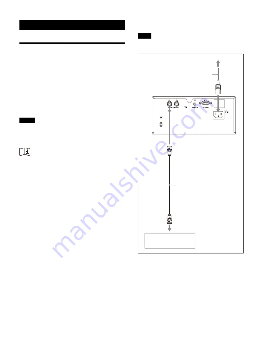
The connection diagrams illustrate how to
connect the input signal source to the printer, how
to connect devices to receive signals output from
the printer, and how to connect a foot switch.
Connect the video equipment which will be used
in actual printing, using the following diagram as
a guide.
Notes
• Turn off the power of each device before
attempting to make any connections.
• Connect the power cord last.
Warning
Using this unit for medical purposes
The connectors on this unit are not isolated.
Do not connect any device other than one which
conforms to IEC 60601-1 standards.
When an information technology device or AV
device that uses an alternating current is
connected, current leakage may result in an
electric shock to the patient or operator.
If use of such a device is unavoidable, isolate its
power supply by connecting an isolation
transformer, or by connecting an isolator between
the connecting cables.
After implementing these measures, confirm that
the reduced risk now conforms to IEC 60601-1
standards.
Connecting video equipment
Note
The printer cannot accommodate 4K video signal
or 3D video signal input.
To video output connector
Video equipment
75
coaxial cable with BNC
connector
5C-FB or equivalent
Power cord
To AC power source
To AC IN
To 3G-SDI (HD/SD) input
Summary of Contents for UP-27MD
Page 90: ......


