3.
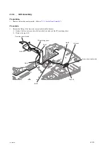
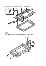
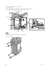
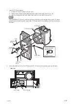
Remove the six screws, and remove the hinge assembly and the 3.5 inch LCD assembly.
Hinge assembly
Locking compound
application area
Locking compound
P2 x 4
[A]
P2 x 4
P2 x 4
3.5 inch LCD assembly
Note
When installing the two screws [A], apply locking compound (about rice grain quantity) to them.
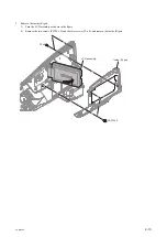
4.
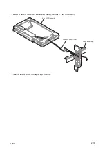
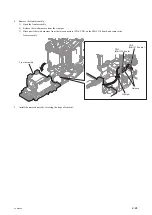
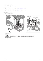
Turn the hinge assembly, and remove the two screws.
Hinge assembly
P1.7 x 2.5
PXW-X500
2-16
Summary of Contents for PXW-X500
Page 1: ...SOLID STATE MEMORY CAMCORDER PXW X500 SERVICE MANUAL 1st Edition ...
Page 4: ......
Page 8: ......
Page 10: ......
Page 54: ......
Page 87: ...3 Remove the tape AS Tape AS PXW X500 2 33 ...
Page 109: ...4 Install the removed parts by reversing the steps of removal PXW X500 2 55 ...
Page 158: ......
Page 183: ......
Page 184: ...PXW X500 SY PXW X500 CN J E 9 878 582 01 Sony Corporation Printed in Japan 2014 11 08 2014 ...


