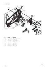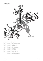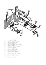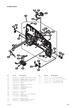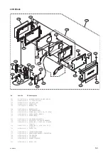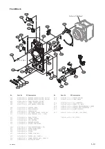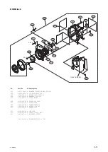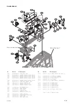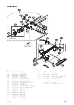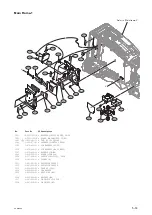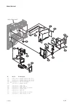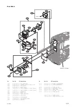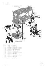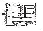
IO Block
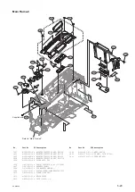
Refer to “Main Frame-4”
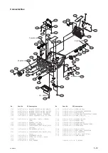
Refer to “Connector box”
1613
1603
1610
1607
1602
1604
1609
1611
1609
1608
1601
1605
1612
1606
Supplied with
1603
No.
Part No.
SP Description
1601
A-1968-119-A s BATTERY HARNESS ASSY
1602
A-2054-866-A s MOUNTED CIRCUIT BOARD, IO-275
1603
A-2058-420-A s MOUNTED CIRCUIT BOARD, CN-3738
1604
A-2063-286-A s MOUNTED CIRCUIT BOARD, DIF-232
1605
1-500-082-11 o CLAMP, SLEEVE FERRITE
1606
1-970-440-11 s SUB HARNESS (IO)
1607
2-635-562-31 s SCREW(M1.7) [P 1.7x4]
1608
3-694-181-03 s TYPE1,AROCK PREP2.6X5
1609
3-742-074-13 s SCREW (+B 3X8)
1610
3-855-938-01 s SCREW [+PSW 2x5]
1611
3-965-077-02 s SCREW, SPECIAL (M2) [M2x2.4]
1612
4-545-527-01 s CAP, CN, REAR
1613
4-674-315-01 s SCREW (M2.6X6)
PXW-X500
5-18
Summary of Contents for PXW-X500
Page 1: ...SOLID STATE MEMORY CAMCORDER PXW X500 SERVICE MANUAL 1st Edition ...
Page 4: ......
Page 8: ......
Page 10: ......
Page 54: ......
Page 87: ...3 Remove the tape AS Tape AS PXW X500 2 33 ...
Page 109: ...4 Install the removed parts by reversing the steps of removal PXW X500 2 55 ...
Page 158: ......
Page 183: ......
Page 184: ...PXW X500 SY PXW X500 CN J E 9 878 582 01 Sony Corporation Printed in Japan 2014 11 08 2014 ...

