2-17. GP-1019 Board, CN-3723 Board
Procedure
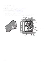
1.
Remove the four screws to detach the handle top cover assembly.
Handle top cover assembly
B2 x 5
2.
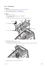
Remove the GP-1019 board and the CN-3723 board.
1) Disconnect the flexible board from the connector on the GP-1019 board.
2) Remove the screw to detach the GP-1019 board.
3) Disconnect the harness from the connector (CN005) on the CN-3723 board.
4) Disconnect the flexible board the connector (CN001) on the CN-3723 board.
5) Remove the screw to detach the CN-3723 board.
GP-1019 board
CN-3723 board
CN001
CN005
Flexible board
Harness
PSW2 x 5
PSW2 x 5
3.
Install the removed parts by reversing the steps of removal.
PXW-X500
2-69
Summary of Contents for PXW-X500
Page 1: ...SOLID STATE MEMORY CAMCORDER PXW X500 SERVICE MANUAL 1st Edition ...
Page 4: ......
Page 8: ......
Page 10: ......
Page 54: ......
Page 87: ...3 Remove the tape AS Tape AS PXW X500 2 33 ...
Page 109: ...4 Install the removed parts by reversing the steps of removal PXW X500 2 55 ...
Page 158: ......
Page 183: ......
Page 184: ...PXW X500 SY PXW X500 CN J E 9 878 582 01 Sony Corporation Printed in Japan 2014 11 08 2014 ...


