10
(GB)
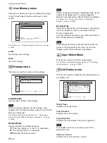
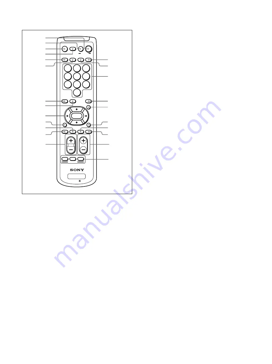
Location and Function of Parts and Controls
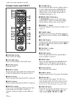
Remote Commander RM-971
1
POWER ON switch
Press to turn on the display.
2
STANDBY button
Press to turn the display to the standby mode.
3
MUTING button
Mutes the sound.
4
DISPLAY button
Displays the input signal information and the picture
mode at the display panel. Press again to clear it.
5
INPUT1 button
Selects the signal input from the INPUT1 connectors.
6
INPUT2 button
Selects the signal input from the INPUT2 connectors.
7
RGB/YUV button
Press to select the format matching that of the input
signal connected to the INPUT1 or INPUT2
connector. Each press toggles between RGB and
YUV.
VOL
CONTRAST
ENTER
DISPLAY
MUTING
1
2
3
4
5
6
7
8
0
9
DISPLAY
STBY
POWER
ID MODE
ON
INPUT 1
INPUT 2
VIDEO
OPTION
RGB/YUV
BRIGHT
H SHIFT
V SHFT
H SIZE
ON
SET
RM-971
OFF
VSIZE
CHROMA
S/VIDEO
ASPECT
MENU
6
5
2
1
3
4
0
7
qs
8
9
qa
qd
qk
ql
w;
qj
qh
wa
ws
wd
qf
qg
8
S/VIDEO button
When the optical adapter has been installed, press to
select the signal input from the COMPOSITE IN
connector or Y/C IN connector from among the
VIDEO connectors. Each press toggles between
COMPOSITE IN and Y/C IN.
9
M
/
m
/
<
/
,
/ENTER buttons
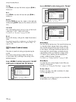
The
M
/
m
/
<
/
,
buttons move the menu cursor
(yellow) and set values, etc. Pressing the ENTER
button enters the selected menu or set contents.
q;
/– button
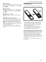
Adjusts the brightness when the picture mode is set to
“User 1-3”.
qa
V SHIFT button
Adjusts the vertical centering. Press this button and
then adjust the vertical centering with the
M
/
m
button
9
.
qs
H SHIFT button
Adjusts the horizontal centering. Press this button and
then adjust the horizontal centering with the
M
/
m
or
<
/
,
button
9
.
qd
/– button
Adjusts the volume.
qf
OPTION button
Selects the signal input from the optional adaptor
when you install it in the unit.
qg
VIDEO button
Selects the signal input from the COMPOSITE IN
connector or Y/C IN connector from among the
VIDEO connectors when you install it in the unit.
qh
Number buttons
Press to enter the index number.
qj
ASPECT button
Changes the aspect ratio of the picture (Wide Mode).
qk
MENU button
Press to make the menu appear. The menu is no
longer displayed when this button is pressed again.
When using the MENU button to return to the previous
menu level, see “Initial Setup Menu” on page 21 (GB).
ql
CHROMA button
Adjusts the chroma when the picture mode is set to
“User 1-3”. Press this button and then adjust the
chroma with the
M
/
m
or
<
/
,
button
9
.
Summary of Contents for PFM-32C1
Page 53: ...53 JP ...
Page 199: ......
Page 297: ......
Page 298: ...2 CS 警告 为避免引发意外的火灾或遭受雷击的危险 请勿将 本机置于雨点所及或者潮湿的地方 输出插座应安装于装置附近使用方便的地方 ...
Page 311: ...15 CS 连接 使用电缆夹 可用附带的电缆夹 5 个 有效地捆扎扬声器电 缆 请按下图所示的方法安装电缆夹 1 2 后视图 取下去皮 纸遮盖物 请按图所示 的方法粘贴 电缆夹 ...
Page 346: ......
Page 347: ......
Page 348: ...Sony Corporation Printed in Japan ...

