


5-11
6. Flange Back Check
Subject
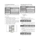
Siemens star
(2.0 m from the front of the lens)
(Luminance: approx. 230 lux)
Measurement Point
Check operation on TV monitor
Measuring Instrument
Specified Value
Focused at the TELE end and WIDE
end.
Note 1:
The front panel block must be assembled.
Switch setting:
1)
STEADY SHOT (Menu display) ..................................... OFF
2)
DIGITAL ZOOM (Menu display) ................................... OFF
Checking method:
1)
Place the Siemens star 2.0m from the front of the lens.
2)
To open the IRIS, decrease the luminous intensity to the
Siemens star up to a point before noise appear on the image.
3)
Shoot the Siemens star with the zoom TELE end.
4)
Turn on the auto focus.
5)
Check that the lens is focused (Note 2).
6)
Select page: 6, address: 21, and set data: 10.
7)
Shoot the Siemens star with the zoom WIDE end.
8)
Observe the TV monitor and check that the lens is focused.
Note 2:
When the auto focus is ON, the lens can be checked if it is focused
or not by observing the data on the page A of the adjustment remote
commander.
1)
Select page: 6, address: 04, and set data: 0F.
2)
Page A shows the state of the focus.
A : 00 : XX
Odd: Focused
Even: Unfocused
Processing after Completing Adjustments:
1)
Select page: 6, address: 04, and set data: 00.
2)
Select page: 6, address: 21, and set data: 00.
7. Picture Frame Setting
Subject
Color bar chart standard picture frame
(1.5m from the front of the lens)
Measurement Point
Video output terminal
Measuring Instrument
Oscilloscope and TV monitor
Specified Value
A=B, C=D, t=0 ± 0.1msec
Setting method:
1)
Adjust the zoom and the camera direction, and set to the
specified position.
2)
Mark the position of the picture frame on the monitor display,
and adjust the picture frame to this position in following
adjustments using “Color bar chart standard picture frame”.
Check on the oscilloscope
1. Horizontal period
Fig. 5-1-6
2. Vertical period
Fig. 5-1-7
Color on the TV monitor
Fig. 5-1-8
A=B
C=D
A
B
C
D
t=0
±
0.1msec
V
Color bar chart picture frame
TV monitor picture frame
Summary of Contents for Handycam Vision DCR-TRV5
Page 10: ...1 2 ...
Page 11: ...1 3 ...
Page 12: ...1 4 ...
Page 13: ...1 5 ...
Page 14: ...1 6 ...
Page 15: ...1 7 ...
Page 16: ...1 8 ...
Page 17: ...1 9 ...
Page 18: ...1 10 ...
Page 19: ...1 11 ...
Page 20: ...1 12 ...
Page 21: ...1 13 ...
Page 22: ...1 14 ...
Page 23: ...1 15 ...
Page 24: ...1 16 ...
Page 25: ...1 17 ...
Page 26: ...1 18 ...
Page 27: ...1 19 ...
Page 28: ...1 20 ...
Page 29: ...1 21 ...
Page 30: ...1 22 ...
Page 31: ...1 23 ...
Page 32: ...1 24 ...
Page 33: ...1 25 ...
Page 34: ...1 26 ...
Page 35: ...1 27 ...
Page 36: ...1 28 ...
Page 37: ...1 29E ...
Page 45: ...DCR TRV5 TRV5E SECTION 3 BLOCK DIAGRAMS 3 1 OVERALL BLOCK DIAGRAM 1 3 1 3 2 3 3 3 4 ...
Page 46: ...DCR TRV5 TRV5E 3 2 OVERALL BLOCK DIAGRAM 2 3 6 3 7 3 8 DCR TRV5 TRV5E ...
Page 47: ...DCR TRV5 TRV5E 3 3 POWER BLOCK DIAGRAM 3 9 3 10 3 11 3 12 3 13E ...
Page 71: ...DCR TRV5 TRV5E 4 75 4 76 4 77 AUDIO PROCESSOR AU 204 ...
Page 73: ...DCR TRV5 TRV5E 4 81 4 82 AUDIO PROCESS IR TRANSMMITER MA 330 ...
Page 107: ...ARRANGEMENT DIAGRAM FOR ADJUSTMENT PARTS VC 207 board SIDE A VC 207 board SIDE B 5 26 ...
Page 131: ...ARRANGEMENT DIAGRAM FOR ADJUSTMENT PARTS VC 207 board SIDE A VC 207 board SIDE B 5 52 ...


