


5-58
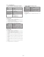
2-2. MSW Code
MSW when errors occur:
Information on MSW (mode SW) when errors occur
MSW when movement starts:
Information on MSW when movements starts when the mechanism position is moved (When the L motor is moved)
MSW of target of movement:
Information on target MSW of movement when the mechanism position is moved
1110=7
1111=F
←
UNLOAD
Lock released
Cassette compartment
LS Chassis movement section
Pinch roller pressing
Tension regulator
EJECT
BL
1010=5
1111=F
ULE
BL
1011=D
1111=F
SR
BL
1001=9
1111=F
HL
BL
0111=E
1111=F
LE
BL
0011=C
1111=F
STOP
BL
1101=B
1111=F
RP
BL
1100=3
1111=F
REW
BL
LOAD
→
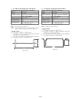
Mechanical Position
A (LSB)
B
C
D (MSB)
Position
EJECT
BL
USE
SR
HL
LE
STOP
RP
REW
Code
7
F
5
D
9
E
C
B
3
Contents
Position at which the cassette component lock is released, at the farthest unload side mechanically
at which the mechanism can move no further in the UNLOAD direction.
BLANK code, at the boundary between codes.
EJECT completion position. When the cassette is ejected, the mechanism will stop at this position.
Cassette IN standby. The guide will start protruding out as the mechanism moves towards the
LOAD position.
Code during loading.
Guide loading are performed here.
Current limiter turned off.
Stop position in the loading state. The pinch roller separates, the tension regulator returns, and the
brake is imposed on both reels.
PB, REC, CUE, PAUSE positions. When pinch roller is pressed, and the tension regulator is ON,
the mechanism is operating at this position in modes in which normal images are shown.
REW position. The tension regulator is half on. This position is not used except for the REW
mode.
Summary of Contents for Handycam Vision DCR-TRV5
Page 10: ...1 2 ...
Page 11: ...1 3 ...
Page 12: ...1 4 ...
Page 13: ...1 5 ...
Page 14: ...1 6 ...
Page 15: ...1 7 ...
Page 16: ...1 8 ...
Page 17: ...1 9 ...
Page 18: ...1 10 ...
Page 19: ...1 11 ...
Page 20: ...1 12 ...
Page 21: ...1 13 ...
Page 22: ...1 14 ...
Page 23: ...1 15 ...
Page 24: ...1 16 ...
Page 25: ...1 17 ...
Page 26: ...1 18 ...
Page 27: ...1 19 ...
Page 28: ...1 20 ...
Page 29: ...1 21 ...
Page 30: ...1 22 ...
Page 31: ...1 23 ...
Page 32: ...1 24 ...
Page 33: ...1 25 ...
Page 34: ...1 26 ...
Page 35: ...1 27 ...
Page 36: ...1 28 ...
Page 37: ...1 29E ...
Page 45: ...DCR TRV5 TRV5E SECTION 3 BLOCK DIAGRAMS 3 1 OVERALL BLOCK DIAGRAM 1 3 1 3 2 3 3 3 4 ...
Page 46: ...DCR TRV5 TRV5E 3 2 OVERALL BLOCK DIAGRAM 2 3 6 3 7 3 8 DCR TRV5 TRV5E ...
Page 47: ...DCR TRV5 TRV5E 3 3 POWER BLOCK DIAGRAM 3 9 3 10 3 11 3 12 3 13E ...
Page 71: ...DCR TRV5 TRV5E 4 75 4 76 4 77 AUDIO PROCESSOR AU 204 ...
Page 73: ...DCR TRV5 TRV5E 4 81 4 82 AUDIO PROCESS IR TRANSMMITER MA 330 ...
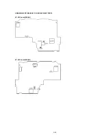
Page 107: ...ARRANGEMENT DIAGRAM FOR ADJUSTMENT PARTS VC 207 board SIDE A VC 207 board SIDE B 5 26 ...
Page 131: ...ARRANGEMENT DIAGRAM FOR ADJUSTMENT PARTS VC 207 board SIDE A VC 207 board SIDE B 5 52 ...


