


5-44
3-5-3.
Base Band Block Adjustments
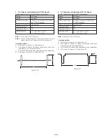
1. Composite Output Y Level Adjustment
(VC-207 Board)
Set the Y signal level of the composite video output signal.
Mode
VTR stop
Signal
No signal
Measurement Point
Video signal terminal of AUDIO/
VIDEO jack (75
Ω
terminated)
Measuring Instrument
Oscilloscope
Adjustment Page
D
Adjustment Address
96
Specified Value
A = 286 ± 6 mV (NTSC)
A = 300 ± 6 mV (PAL)
Note:
Insert a plug in the AUDIO/VIDEO jack.
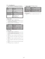
Adjusting method:
1)
Select page: 0, address: 01, and set data: 01.
2)
Select page: D, address: 96, change the data and set the sync
signal level (A) to the specified value.
3)
Press the PAUSE button of the adjustment remote commander.
4)
Select page: 0, address: 01, and set data: 00.
5)
Perform “Composite Output Chroma Level Adjustment”.
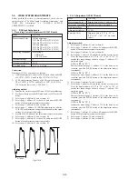
Fig. 5-3-8
A
H
2. Composite Output Chroma Level Adjustment
(VC-207 Board)
Set the chroma signal level of the composite video output signal.
Mode
VTR stop
Signal
No signal
Measurement Point
Video signal terminal of AUDIO/
VIDEO jack (75
Ω
terminated)
Measuring Instrument
Oscilloscope
Adjustment Page
D
Adjustment Address
97
Specified Value
A = 286 ± 6 mV (NTSC)
A = 300 ± 6 mV (PAL)
Note 1:
Insert a plug in the AUDIO/VIDEO jack.
Note 2:
Perform “Composite Output Y Level Adjustment” before this
adjustment.
Adjusting method:
1)
Select page: 0, address: 01, and set data: 01.
2)
Select page: D, address: 97, change the data and set the burst
signal level (A) to the specified value.
3)
Press the PAUSE button of the adjustment remote commander.
4)
Select page: 0, address: 01, and set data: 00.
5)
Perform “S-C Output Level Adjustment”.
Fig. 5-3-9
A
H
Summary of Contents for Handycam Vision DCR-TRV5
Page 10: ...1 2 ...
Page 11: ...1 3 ...
Page 12: ...1 4 ...
Page 13: ...1 5 ...
Page 14: ...1 6 ...
Page 15: ...1 7 ...
Page 16: ...1 8 ...
Page 17: ...1 9 ...
Page 18: ...1 10 ...
Page 19: ...1 11 ...
Page 20: ...1 12 ...
Page 21: ...1 13 ...
Page 22: ...1 14 ...
Page 23: ...1 15 ...
Page 24: ...1 16 ...
Page 25: ...1 17 ...
Page 26: ...1 18 ...
Page 27: ...1 19 ...
Page 28: ...1 20 ...
Page 29: ...1 21 ...
Page 30: ...1 22 ...
Page 31: ...1 23 ...
Page 32: ...1 24 ...
Page 33: ...1 25 ...
Page 34: ...1 26 ...
Page 35: ...1 27 ...
Page 36: ...1 28 ...
Page 37: ...1 29E ...
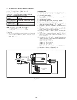
Page 45: ...DCR TRV5 TRV5E SECTION 3 BLOCK DIAGRAMS 3 1 OVERALL BLOCK DIAGRAM 1 3 1 3 2 3 3 3 4 ...
Page 46: ...DCR TRV5 TRV5E 3 2 OVERALL BLOCK DIAGRAM 2 3 6 3 7 3 8 DCR TRV5 TRV5E ...
Page 47: ...DCR TRV5 TRV5E 3 3 POWER BLOCK DIAGRAM 3 9 3 10 3 11 3 12 3 13E ...
Page 71: ...DCR TRV5 TRV5E 4 75 4 76 4 77 AUDIO PROCESSOR AU 204 ...
Page 73: ...DCR TRV5 TRV5E 4 81 4 82 AUDIO PROCESS IR TRANSMMITER MA 330 ...
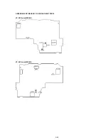
Page 107: ...ARRANGEMENT DIAGRAM FOR ADJUSTMENT PARTS VC 207 board SIDE A VC 207 board SIDE B 5 26 ...
Page 131: ...ARRANGEMENT DIAGRAM FOR ADJUSTMENT PARTS VC 207 board SIDE A VC 207 board SIDE B 5 52 ...


