


5-24
7. V-COM Level Adjustment (PD-100 board)
Set the common electrode drive signal level of LCD to the specified
value.
Mode
VTR playback
Signal
Alignment tape:
For audio operation check
(XH5-3 (NTSC))
(XH5-3P (PAL))
Measurement Point
Pin
4
of CN5501 (PANEL COM)
Measuring Instrument
Oscilloscope
Adjustment Page
D
Adjustment Address
64
Specified Value
A = 4.90 ± 0.05V
Note:
Perform “Bright Adjustment” and “Contrast Adjustment” before this
adjustment.
Adjusting method:
1)
Select page: 0, address: 01, and set data: 01.
2)
Select page: D, address: 64, change the data and set the PANEL
COM signal level (A) to the specified value.
3)
Press the PAUSE button of the adjustment remote commander.
4)
Select page: 0, address: 01, and set data: 00.
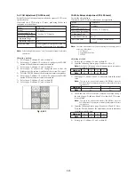
Fig. 5-1-20
A
2H
8. Color Adjustment (PD-100 board)
Set the color saturation to the standard value. If deviated, the color
will be to dark or light.
Mode
VTR playback
Signal
Alignment tape:
For audio operation check
(XH5-3 (NTSC))
(XH5-3P (PAL))
Measurement Point
Pin
3
of CN5501 (VG)
External trigger : Pin
4
of CN5501
(PANEL COM)
Measuring Instrument
Oscilloscope
Adjustment Page
D
Adjustment Address
6D
Specified Value
A = 0.15 ± 0.05V (NTSC)
A = 0.20 ± 0.05V (PAL)
Adjusting method:
1)
Select page: 0, address: 01, and set data: 01.
2)
Select page: 2, address: 1F, set data: 02.
3)
NTSC model:
Select page: D, address: 6D, change the data and set the voltage
(A) between the white and green to the specified value.
PAL model:
Select page: D, address: 6D, change the data and set the voltage
(A) between the yellow and green to the specified value.
4)
Press the PAUSE button of the adjustment remote commander.
5)
Select page: 2, address: 1F, set data: 00.
6)
Select page: 0, address: 01, and set data: 00.
For NTSC model
For PAL model
Fig. 5-1-21
White (75%)
Green
A
2H
Yellow
Green
2H
A
Summary of Contents for Handycam Vision DCR-TRV5
Page 10: ...1 2 ...
Page 11: ...1 3 ...
Page 12: ...1 4 ...
Page 13: ...1 5 ...
Page 14: ...1 6 ...
Page 15: ...1 7 ...
Page 16: ...1 8 ...
Page 17: ...1 9 ...
Page 18: ...1 10 ...
Page 19: ...1 11 ...
Page 20: ...1 12 ...
Page 21: ...1 13 ...
Page 22: ...1 14 ...
Page 23: ...1 15 ...
Page 24: ...1 16 ...
Page 25: ...1 17 ...
Page 26: ...1 18 ...
Page 27: ...1 19 ...
Page 28: ...1 20 ...
Page 29: ...1 21 ...
Page 30: ...1 22 ...
Page 31: ...1 23 ...
Page 32: ...1 24 ...
Page 33: ...1 25 ...
Page 34: ...1 26 ...
Page 35: ...1 27 ...
Page 36: ...1 28 ...
Page 37: ...1 29E ...
Page 45: ...DCR TRV5 TRV5E SECTION 3 BLOCK DIAGRAMS 3 1 OVERALL BLOCK DIAGRAM 1 3 1 3 2 3 3 3 4 ...
Page 46: ...DCR TRV5 TRV5E 3 2 OVERALL BLOCK DIAGRAM 2 3 6 3 7 3 8 DCR TRV5 TRV5E ...
Page 47: ...DCR TRV5 TRV5E 3 3 POWER BLOCK DIAGRAM 3 9 3 10 3 11 3 12 3 13E ...
Page 71: ...DCR TRV5 TRV5E 4 75 4 76 4 77 AUDIO PROCESSOR AU 204 ...
Page 73: ...DCR TRV5 TRV5E 4 81 4 82 AUDIO PROCESS IR TRANSMMITER MA 330 ...
Page 107: ...ARRANGEMENT DIAGRAM FOR ADJUSTMENT PARTS VC 207 board SIDE A VC 207 board SIDE B 5 26 ...
Page 131: ...ARRANGEMENT DIAGRAM FOR ADJUSTMENT PARTS VC 207 board SIDE A VC 207 board SIDE B 5 52 ...


