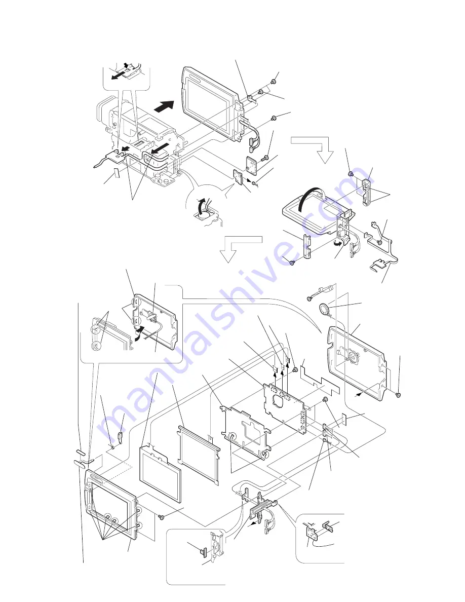
2-5
a
a
Board
PD-100
2
Press the claw
3
Pull
1
Cushion
5
FP-699 flexible board
PANEL CLOSE switch (S002) block
6
M2
×
2.5
@º
M1.7
×
2.5
#¢
Lithium battery
lid
#§
Harness SP-155
#∞
Insert a tweezers tip
or the like and snap
it out
8
Turn the LCD block in
the direction of the arrow
!¡
Hinge cover (front)
!¡
Hinge cover (rear)
!º
Claws
!∞
Claws
@¡
Claws
#º
Claws
!£
FP-699 flexible board
7
Turn the tilt base
in the direction
of the arrow
!§
Remove the LCD cabinet (R) assembly
in the direction of the arrow while taking
care not to damage the harness (SP-154)
!§
LCD cabinet (R)
assembly
@™
LCD cabinet (L)
#¡
LCD frame
@¢
ND901
@£
LCD901
@•
Hinge assembly
*
1
@§
Harness SP-152
(from CN5802)
@∞
Harness blind tape
!•
PD flexible
sheet
#™
PD-100 board
!ª
From CN5501
!ª
From CN5804
!ª
From CN5701
Remove the flexible board
connected to the LCD,
from the cabinet (R) assembly
Harness
4
M1.7
×
2
6
M2
×
2.5
#£
2
×
5
#¶
LI-65 board
9
M1.7
×
2
9
M1.7
×
2
!™
M1.7
×
2
@ª
M1.7
×
2
@¶
M1.7
×
2
!¢
M1.7
×
2
@§
Harness SP-153
(from CN5801)
!¶
Harness SP-154
(from CN5803)
Hinge cover (lower)
(3-989-856-01)
Melt them by soldering iron or
attach them with adhesive agent
Hinge assembly
(X-3948-660-1)
*
1 When replacing the hinge assembly, replace the hinge cover (lower)
and sleeve harness at the same time because the hinge assembly
does not include the hinge cover (lower) and sleeve harness.
Speaker
Speaker
LCD lock spring
Open button
Control switch block (VL4680)
Cushion (VL)
Sleeve harness
(3-051-046-01)
Attach sleeve harness to
hinge assembly by
adhesive agent.
2-7. REMOVAL OF LCD BLOCK
Summary of Contents for Handycam Vision DCR-TRV5
Page 10: ...1 2 ...
Page 11: ...1 3 ...
Page 12: ...1 4 ...
Page 13: ...1 5 ...
Page 14: ...1 6 ...
Page 15: ...1 7 ...
Page 16: ...1 8 ...
Page 17: ...1 9 ...
Page 18: ...1 10 ...
Page 19: ...1 11 ...
Page 20: ...1 12 ...
Page 21: ...1 13 ...
Page 22: ...1 14 ...
Page 23: ...1 15 ...
Page 24: ...1 16 ...
Page 25: ...1 17 ...
Page 26: ...1 18 ...
Page 27: ...1 19 ...
Page 28: ...1 20 ...
Page 29: ...1 21 ...
Page 30: ...1 22 ...
Page 31: ...1 23 ...
Page 32: ...1 24 ...
Page 33: ...1 25 ...
Page 34: ...1 26 ...
Page 35: ...1 27 ...
Page 36: ...1 28 ...
Page 37: ...1 29E ...
Page 45: ...DCR TRV5 TRV5E SECTION 3 BLOCK DIAGRAMS 3 1 OVERALL BLOCK DIAGRAM 1 3 1 3 2 3 3 3 4 ...
Page 46: ...DCR TRV5 TRV5E 3 2 OVERALL BLOCK DIAGRAM 2 3 6 3 7 3 8 DCR TRV5 TRV5E ...
Page 47: ...DCR TRV5 TRV5E 3 3 POWER BLOCK DIAGRAM 3 9 3 10 3 11 3 12 3 13E ...
Page 71: ...DCR TRV5 TRV5E 4 75 4 76 4 77 AUDIO PROCESSOR AU 204 ...
Page 73: ...DCR TRV5 TRV5E 4 81 4 82 AUDIO PROCESS IR TRANSMMITER MA 330 ...
Page 107: ...ARRANGEMENT DIAGRAM FOR ADJUSTMENT PARTS VC 207 board SIDE A VC 207 board SIDE B 5 26 ...
Page 131: ...ARRANGEMENT DIAGRAM FOR ADJUSTMENT PARTS VC 207 board SIDE A VC 207 board SIDE B 5 52 ...

