


6-3
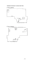
6-1-3. LCD PANEL SECTION
a
101
102
103
104
105
PD-100
Board
106
106
106
106
107
108
109
110
111
112
113
114
115
116
121
121
106
106
106
117
118
119
SP901
LCD901
ND901
not supplied
120
a
*
1
Hinge cover (lower)
(3-989-856-01)
Melt them by soldering iron or
attach them with adhesive agent
Hinge assembly
(X-3948-660-1)
122
Sleeve harness
(3-051-046-01)
Attach 122 to
117 by adhesive agent.
*
1 When replacing the hinge assembly, replace the hinge cover (lower)
and sleeve harness at the same time because the hinge assembly
does not include the hinge cover (lower) and sleeve harness.
Ref. No.
Part No.
Description
Remarks
Ref. No.
Part No.
Description
Remarks
101
3-989-808-01 CABINET (L), LCD
102
1-475-745-21 SWITCH BLOCK, CONTROL (VL4680)
103
3-989-875-01 SPRING, LCD LOCK
104
3-989-809-01 BUTTON, OPEN
*
105
3-989-823-01 FRAME, LCD
106
3-989-735-11 SCREW (M1.7), LOCK ACE, P2
107
1-958-473-11 HARNESS (SP-154)
*
108
3-989-598-01 SHEET, PD FLEXIBLE
109
X-3948-849-1 CABINET (R) ASSY, LCD (TRV5/TRV5E:E,HK,JE)
109
X-3948-843-1 CABINET (R) ASSY, LCD (TRV5E:AEP,UK)
110
3-989-861-01 TAPE, HARNESS BLIND
111
1-958-471-11 HARNESS (SP-152)
112
1-958-472-11 HARNESS (SP-153)
113
A-7073-615-A PD-100 BOARD, COMPLETE
114
3-989-824-01 COVER (FRONT), HINGE
115
3-989-856-01 COVER (LOWER), HINGE
116
1-669-144-21 FP-699 FLEXIBLE BOARD
117
X-3948-660-1 HINGE ASSY
118
3-989-825-01 COVER (REAR), HINGE
119
3-989-735-01 SCREW (M1.7), LOCK ACE, P2
*
120
3-051-814-01 CUSHION (VL)
121
3-831-441-99 CUSHION (SP)
122
3-051-046-01 SLEEVE, HARNESS
LCD901 1-803-033-21 INDICATOR MODULE, LIQUID CRYST
!
ND901
1-517-754-11 TUBE, FLUORESCENT,COLD CATHODE
SP901
1-505-862-11 SPEAKER (2.0CM)
Note :
The components identified by
mark
!
or dotted line with mark
!
are critical for safety.
Replace only with part number
specified.
Note :
Les composants identifiés par
une marque
!
sont critiques
pour la sécurité.
Ne les remplacer que par une
pièce portant le numéro spécifié.
Summary of Contents for Handycam Vision DCR-TRV5
Page 10: ...1 2 ...
Page 11: ...1 3 ...
Page 12: ...1 4 ...
Page 13: ...1 5 ...
Page 14: ...1 6 ...
Page 15: ...1 7 ...
Page 16: ...1 8 ...
Page 17: ...1 9 ...
Page 18: ...1 10 ...
Page 19: ...1 11 ...
Page 20: ...1 12 ...
Page 21: ...1 13 ...
Page 22: ...1 14 ...
Page 23: ...1 15 ...
Page 24: ...1 16 ...
Page 25: ...1 17 ...
Page 26: ...1 18 ...
Page 27: ...1 19 ...
Page 28: ...1 20 ...
Page 29: ...1 21 ...
Page 30: ...1 22 ...
Page 31: ...1 23 ...
Page 32: ...1 24 ...
Page 33: ...1 25 ...
Page 34: ...1 26 ...
Page 35: ...1 27 ...
Page 36: ...1 28 ...
Page 37: ...1 29E ...
Page 45: ...DCR TRV5 TRV5E SECTION 3 BLOCK DIAGRAMS 3 1 OVERALL BLOCK DIAGRAM 1 3 1 3 2 3 3 3 4 ...
Page 46: ...DCR TRV5 TRV5E 3 2 OVERALL BLOCK DIAGRAM 2 3 6 3 7 3 8 DCR TRV5 TRV5E ...
Page 47: ...DCR TRV5 TRV5E 3 3 POWER BLOCK DIAGRAM 3 9 3 10 3 11 3 12 3 13E ...
Page 71: ...DCR TRV5 TRV5E 4 75 4 76 4 77 AUDIO PROCESSOR AU 204 ...
Page 73: ...DCR TRV5 TRV5E 4 81 4 82 AUDIO PROCESS IR TRANSMMITER MA 330 ...
Page 107: ...ARRANGEMENT DIAGRAM FOR ADJUSTMENT PARTS VC 207 board SIDE A VC 207 board SIDE B 5 26 ...
Page 131: ...ARRANGEMENT DIAGRAM FOR ADJUSTMENT PARTS VC 207 board SIDE A VC 207 board SIDE B 5 52 ...


