


5-33
3-1-5.
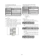
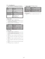
Alignment Tapes
Use the alignment tapes shown in the following table.
Use tapes specified in the signal column of each adjustment.
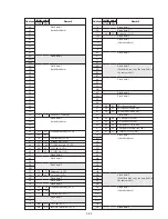
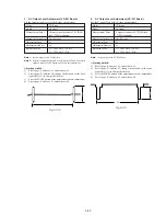
Fig. 5-3-2 shows the 75% color bar signals recorded on the alignment
tape for Audio Operation Check.
Note:
Measure with video terminal (Terminated at 75
Ω
)
Use
Tape path adjustment
Switching position adjustment
Audio system adjustment
Operation check
BIST check
Name
Tracking standard (XH2-1)
SW/OL standard (XH2-3)
Audio operation check
(XH5-3 (NTSC), XH5-3P (PAL))
System operation check
(XH5-5 (NTSC), XH5-5P (PAL))
BIST check
(XH5-6 (NTSC), XH5-6P (PAL))
1V
0.7V
0.3V
White (100%)
Y
e
llo
w
Cy
an
Green
Magenta
Red
Blue
Burst signal
Horizontal sync signal
0.3V
(100%)
Y
ello
w
Cy
an
Green
Magenta
Red
Blue
White
Blac
k
1V
0.714V
0.286V
White (75%)
White (100%)
Y
ello
w
Cy
an
Green
Magenta
Red
Blue
Burst signal
0.286V
Q
I
Horizontal sync signal
(75%)
White
Y
ello
w
Cy
an
Green
Magenta
Red
Blue
Q
I
White
(100%)
Black
For NTSC model
For PAL model
Color bar signal waveform
Color bar pattern
Color bar signal waveform
Color bar pattern
Fig. 5-3-2 Color bar signal of alignment tapes
3-1-6.
Output Level and Impedance
Video output
Special stereo mini jack
Video signal:
1 Vp-p, 75
Ω
unbalanced,
sync negative
S video output
4-pin mini DIN
Luminance signal:
1 Vp-p, 75
Ω
unbalanced,
sync negative
Chrominance signal: 0.286 Vp-p, 75
Ω
unbalanced (NTSC)
: 0.300 Vp-p, 75
Ω
unbalanced (PAL)
Audio output
Special stereo mini jack
Output level: 327 mV (at load impedance 47 k
Ω
)
Output impedance: Below 2.2 k
Ω
Summary of Contents for Handycam Vision DCR-TRV5
Page 10: ...1 2 ...
Page 11: ...1 3 ...
Page 12: ...1 4 ...
Page 13: ...1 5 ...
Page 14: ...1 6 ...
Page 15: ...1 7 ...
Page 16: ...1 8 ...
Page 17: ...1 9 ...
Page 18: ...1 10 ...
Page 19: ...1 11 ...
Page 20: ...1 12 ...
Page 21: ...1 13 ...
Page 22: ...1 14 ...
Page 23: ...1 15 ...
Page 24: ...1 16 ...
Page 25: ...1 17 ...
Page 26: ...1 18 ...
Page 27: ...1 19 ...
Page 28: ...1 20 ...
Page 29: ...1 21 ...
Page 30: ...1 22 ...
Page 31: ...1 23 ...
Page 32: ...1 24 ...
Page 33: ...1 25 ...
Page 34: ...1 26 ...
Page 35: ...1 27 ...
Page 36: ...1 28 ...
Page 37: ...1 29E ...
Page 45: ...DCR TRV5 TRV5E SECTION 3 BLOCK DIAGRAMS 3 1 OVERALL BLOCK DIAGRAM 1 3 1 3 2 3 3 3 4 ...
Page 46: ...DCR TRV5 TRV5E 3 2 OVERALL BLOCK DIAGRAM 2 3 6 3 7 3 8 DCR TRV5 TRV5E ...
Page 47: ...DCR TRV5 TRV5E 3 3 POWER BLOCK DIAGRAM 3 9 3 10 3 11 3 12 3 13E ...
Page 71: ...DCR TRV5 TRV5E 4 75 4 76 4 77 AUDIO PROCESSOR AU 204 ...
Page 73: ...DCR TRV5 TRV5E 4 81 4 82 AUDIO PROCESS IR TRANSMMITER MA 330 ...
Page 107: ...ARRANGEMENT DIAGRAM FOR ADJUSTMENT PARTS VC 207 board SIDE A VC 207 board SIDE B 5 26 ...
Page 131: ...ARRANGEMENT DIAGRAM FOR ADJUSTMENT PARTS VC 207 board SIDE A VC 207 board SIDE B 5 52 ...


