


5-49
3. IR Audio Deviation Adjustment (MA-330 board)
Mode
Camera standby
Signal
400Hz, –66dBs : L and R of MIC jack
Measurement Point
AUDIO L terminal and AUDIO R
terminal of IR receiver jig
(Terminated at 47k
Ω
)
Measuring Instrument
Audio level meter
Adjustment Page
D
Adjustment Address
92
Specified Value
Signal level: –7.5 ± 1.0 dBs
Level difference of L and R: Below 2dB
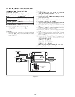
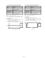
Connection of Equipment:
Connect the measuring device as shown in the following figure,
and adjust.
Adjusting method:
1)
Select page: 0, address: 01, and set data: 01.
2)
Connect the audio level meter to the AUDIO L terminal of the
IR receiver jig.
3)
Select page: D, address: 92, change the data and set the 400Hz
audio signal level to the specified value.
4)
Press the PAUSE button of the adjustment remote commander.
5)
Connect the audio level meter to the AUDIO R terminal of the
IR receiver jig.
6)
Check that the 400Hz audio signal level is within the specified
value. If outside, repeat from step 2).
7)
Select page: 0, address: 01, and set data: 00.
Main unit
Audio oscillator
Left
Right
Attenuator
MIC
IR receiver jig
AUDIO OUT
L
R
Audio level meter
47k
Ω
600
Ω
600
Ω
: 270
Ω
(1-249-410-11) + 330
Ω
(1-249-411-11)
47k
Ω
(1-249-437-11)
Fig. 5-3-15
Summary of Contents for Handycam Vision DCR-TRV5
Page 10: ...1 2 ...
Page 11: ...1 3 ...
Page 12: ...1 4 ...
Page 13: ...1 5 ...
Page 14: ...1 6 ...
Page 15: ...1 7 ...
Page 16: ...1 8 ...
Page 17: ...1 9 ...
Page 18: ...1 10 ...
Page 19: ...1 11 ...
Page 20: ...1 12 ...
Page 21: ...1 13 ...
Page 22: ...1 14 ...
Page 23: ...1 15 ...
Page 24: ...1 16 ...
Page 25: ...1 17 ...
Page 26: ...1 18 ...
Page 27: ...1 19 ...
Page 28: ...1 20 ...
Page 29: ...1 21 ...
Page 30: ...1 22 ...
Page 31: ...1 23 ...
Page 32: ...1 24 ...
Page 33: ...1 25 ...
Page 34: ...1 26 ...
Page 35: ...1 27 ...
Page 36: ...1 28 ...
Page 37: ...1 29E ...
Page 45: ...DCR TRV5 TRV5E SECTION 3 BLOCK DIAGRAMS 3 1 OVERALL BLOCK DIAGRAM 1 3 1 3 2 3 3 3 4 ...
Page 46: ...DCR TRV5 TRV5E 3 2 OVERALL BLOCK DIAGRAM 2 3 6 3 7 3 8 DCR TRV5 TRV5E ...
Page 47: ...DCR TRV5 TRV5E 3 3 POWER BLOCK DIAGRAM 3 9 3 10 3 11 3 12 3 13E ...
Page 71: ...DCR TRV5 TRV5E 4 75 4 76 4 77 AUDIO PROCESSOR AU 204 ...
Page 73: ...DCR TRV5 TRV5E 4 81 4 82 AUDIO PROCESS IR TRANSMMITER MA 330 ...
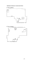
Page 107: ...ARRANGEMENT DIAGRAM FOR ADJUSTMENT PARTS VC 207 board SIDE A VC 207 board SIDE B 5 26 ...
Page 131: ...ARRANGEMENT DIAGRAM FOR ADJUSTMENT PARTS VC 207 board SIDE A VC 207 board SIDE B 5 52 ...


