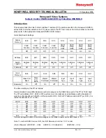
3-31
DNW-A100/A50/A45
DNW-A100P/A50P/A45P
6. LAU PB Phase Adjustment
1.
Connect and set the oscilloscope as follows:
X-Y mode
CH-1: Pin 2 (X) of AUDIO OUTPUT CH1 connector
GND: Pin 1 (G) of it, AC
CH-2: Pin 2 (X) of AUDIO OUTPUT CH2 connector
GND: Pin 1 (G) of it, AC
When the VTR is equipped with BKNW-105, connect
the oscilloscope to the following connectors.
CH-1: MONITOR OUTPUT L connector
CH-2: MONITOR OUTPUT R connector
n
An XLR-to-pigtail cable is very convenient to connect
between the oscilloscope and the above-mentioned
connectors.
Prepare two XLR-to-pigtail cables for this adjustment.
And connect the XLR plug end of the cable to above-
mentioned connectors and the pigtailed end to the
oscilloscope. The cables for CH-1 and CH-2 shall be
the same in length and same wire color on the pigtailed
end.
2.
For DNW-A100/A50/A45: Play back the 10 kHz,
_
10
VU portion (3:00 to 4:55) of the alignment tape CR8-
1A in PLAY mode.
For DNW-A100P/A50P/A45P: Play back the 15 kHz,
0 VU portion (3:00 to 4:55) of the alignment tape
CR8-1B PS in PLAY mode.
3.
Watch the lissajous waveform on the oscilloscope.
4.
Align the vertical and horizontal amplitudes of
lissajous waveform to 60 mm square with the VOLTS/
DIV and VAR controls of the oscilloscope.
5.
Minimize the phase difference A of lissajous wave-
form.
Adj. point:
1
RV603/APR-12(F-1)
Specification: A
<
5.2 mm (Refer to Figure 3.)
Oscilloscope
5. LAU PB Level Adjustment
1.
Set the audio analyzer as follows:
Function mode: LEVEL, dBm (600
Z
)
Input filter:
80 kHz LPF
CH2 adjustment
2.
Connect the audio analyzer’s input to AUDIO OUT-
PUT CH2 connector.
When the VTR is equipped with BKNW-105 (optional
kit), connect the audio analyzer to MONITOR OUT-
PUT R connector.
3.
Play back the 1 kHz, 0 VU portion (0:00 to 2:55) of
the following alignment tape in PLAY mode.
For DNW-A100/A50/A45:
CR8-1A
For DNW-A100P/A50P/A45P: CR8-1B PS
4.
Adjust the audio level on the audio analyzer.
Adj. point:
1
RV605/APR-12(F-1)
Specification:
+
4.0
±
0.2 dBm (at 600
Z
load)
CH1 adjustment
5.
Connect the audio analyzer’s input to AUDIO OUT-
PUT CH1 connector.
When the VTR is equipped the BKNW-105, connect it
to MONITOR OUTPUT L connector
6.
Play back the 1 kHz, 0 VU portion (0:00 to 2:55) of
the CR8-1A or CR8-1B PS in PLAY mode.
7.
Adjust the audio level on the audio analyzer.
Adj. point:
1
RV504/APR-12(B-1)
Specification:
+
4.0
±
0.2 dBm (at 600
Z
load)
APR-12 Board (Side A)
S600
RV600
RV601
RV602
TP600
RV603
TP601
RV604
RV605
E600
TP501
RV503
TP500
RV501
RV502
RV500
S500
RV203
E200
TP700 TP560
RV202
COR201
20 18 16
RV200
TP201
TP200
RV201
RV103
E100
RV102
COR200
0
–3
–20
+4
COR101
20 18 16
TP101
RV100
TP100
RV101
COR100
0
–3
–20
+4
COR400
16 18 20
COR401
VAR (R)
UNITY (R)
TP400
RV400
E400
TP701
COR402
+4
0
–3
–20
COR300
16 18 20
COR301
VAR (L)
UNITY (L)
TP300
RV300
E300
COR302
+4
0
–3
–20
1
2
3
4
5
6
7
A
A
B
RV504
E500
C
D
E
F
G
A No.
LOTNO,
S NO,
APR–12
1-661-132-
MADE IN JAPAN
>EP–GW<
3-6. Audio System Adjustment (APR-12/13 Boards)
3-6-9. LAU PB System Adjustment (APR-12 Board)
Figure 3. Lissajous Waveform of LAU PB Phase Adjustment
60 mm
60 mm
A